AERMEC NLC Installation Manual Download Page 4

4 - EN

EN

NLC_A cod: 1606.4037360_00

1. 

GENERAL WARNINGS FOR THE INSTALLER

The NLC AERMEC units are constructed according to the recognised 

technical standards and safety regulations. They have been designed for 

air conditioning and must be used for this purpose in accordance with 

their technical features. The company shall not be contractually or non-

contractually liable for any damage to people, animals or objects, for 

failures caused by errors during installation, adjustment and maintenance 

or incorrect use. All the uses not expressly indicated in this manual are not 

allowed.

PRESERVATION OF THE DOCUMENTATION

Deliver the following instructions plus all the complementary documentation 

to the system user, who shall be responsible for keeping the instructions so 

that they are always available when needed. 

Read carefully this chapter; all the procedures must be carried out by 

qualified personnel according to the regulations in force in the various 

countries. 

The warranty of the device does not in any case cover costs incurred as a 

result of motorised ladders, scaffolding or any other lifting systems made 

necessary to carry out the operations under warranty. 

Do not modify or tamper with the appliance as dangerous situations may 

be created and the manufacturer will not be liable for any damage caused. 

The warranty shall not be valid if the indications mentioned above are not 

observed.

SAFETY PRECAUTIONS AND INSTALLATION REGULATIONS 


The appliance must be installed by an authorised and qualified technician, 

in compliance with the national legislation in force in the country of 

destination.  

Aermec shall not be held responsible for any damage whatsoever resulting 

from the non-compliance with these instructions.

Before starting any kind of work, it is necessary TO READ CAREFULLY THE 

INSTRUCTIONS, AND TO PERFORM THE SAFETY CHECKS TO REDUCE ALL 

HAZARDS TO A MINIMUM. All the personnel in charge must be aware of 

the operations and the risks that may arise when all the unit installation 

operations begin.

WARRANTY

The warranty of the device does not cover costs incurred as a result of 

ladders, scaffolding or any other lifting systems made necessary to carry out 

operations under warranty.

Do not modify or tamper with the chiller as this may cause dangerous 

situations and the manufacturer will not be liable for any damage caused. 

The warranty shall not be valid if the indications mentioned above are not 

observed.

SAFETY PRECAUTIONS AND INSTALLATION REGULATIONS

The unit must be installed by an authorised and qualified technician, in 

compliance with the national legislation in force in the country of destination 

(MD 329/2004). AERMEC shall not be held responsible for any damage 

whatsoever resulting from the non-compliance with these instructions.

Before starting any work, it is necessary TO READ CAREFULLY THE 

INSTRUCTIONS, AND TO PERFORM THE SAFETY CHECKS TO AVOID ANY 

RISKS.

All the personnel in charge must be aware of the operations and the risks 

that may arise when all the unit installation operations begin.

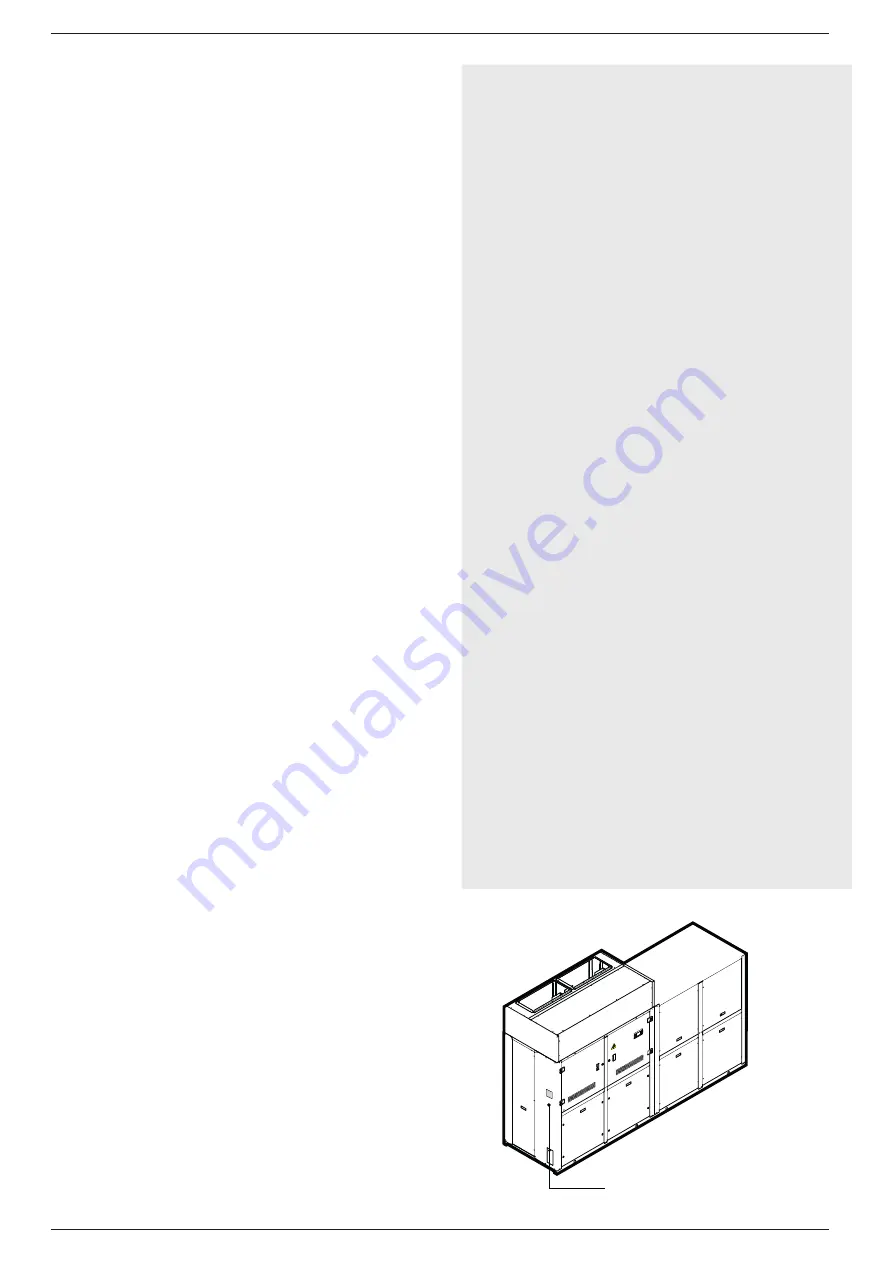
PRODUCT IDENTIFICATION

The units can be identified using:

PACKAGING LABEL


- that includes the product identification data

TECHNICAL LABEL

REGULATIONS RESPECTED 

IN DESIGNING AND CONSTRUCTING 

THE UNIT

Standards and Directives respected on

designing and constructing the unit:

PROTECTION RATING

IP 20

ACOUSTIC PART:

1. ISO DIS 9614/2

(INTENSIMETRIC METHOD))

2. SOUND POWER (EN ISO 9614-2)

3. SOUND PRESSURE (EN ISO 3744)

REFRIGERANT GAS:

This unit contains fluoride gases with

greenhouse effect covered by the

Kyoto Protocol. Maintenance and

disposal must only be performed by

qualified staff.

STANDARD:

UL 1995

Heating and cooling equipment.

ANSI/NFPA

Standard 70 National Electrical code

(N.E.C.).

CSA C.22.1.- C.22.2

Safety Standard Electrical Installation.

REFRIGERANT GAS

This unit contains fluorinated greenhouse gases covered by the Kyoto 

Protocol. Maintenance and disposal operations must be only carried out by 

qualified personnel in compliance with the standards in force.

WARNING

The refrigerant circuit is pressurised. Work on the appliance can be carried 

out only by an authorised ATS technician or by a qualified technician.

GAS R410A 

The chiller is delivered with the necessary amount of R410A refrigerant 

for its operation. It is a chlorine-free refrigerant that does not damage 

the ozone layer. R410A is not flammable. However, all the maintenance 

operations must only be carried out by a specialised technician with the 

suitable protection equipment

RISK OF ELECTRIC DISCHARGE!

Before opening the chiller, the unit must be completely disconnected from 

the mains power supply.

Technical Label

Summary of Contents for NLC

Page 1: ...Installation Manual IT EN FR Chiller Air Water Indoor Installation 1606 4037360_00 NLC 0750 A...

Page 2: ...g top quality materials and advanced technologies We constantly monitor the quality level and as a result AERMEC products are synonymous with Safety Quality and Reliability Aermec reserves the right t...

Page 3: ...rical wirings 8 9 Electrical data table 9 10 Electronic regulation pCO5 10 11 Loading the system 16 12 System discharge 16 13 Draining the machine 16 14 Control and first start up 17 15 Calibration of...

Page 4: ...not modify or tamper with the chiller as this may cause dangerous situations and the manufacturer will not be liable for any damage caused The warranty shall not be valid if the indications mentioned...

Page 5: ...ric part is allowed 4 MINIMUM TECHNICAL CLEARANCES 500 mm 19 69 in 800 mm 31 50 in 800 mm 31 50 in 1000 mm 39 37 in 5 OPERATION OF THE NLC UNIT The chillers and the heat pumps of the NLC range are air...

Page 6: ...rameter fans max Volts V 0750 69000 40611 866 6 6 8 3 7 5 8 7 8 3 9 2 9 2 9 6 10 0 10 0 400 WARNING The weight of the piping must not be borne by the appliance WARNING Remove the safety protections be...

Page 7: ...TALLER 3 Air drain valve 4 Pump 5 Safety valve obligatory 6 Water filter obligatory 7 Anti vibration joints 8 Pressure gauge 9 Flow switch obligatory 10 Water drain cock 11 Expansion tank 12 Electric...

Page 8: ...n the front panel Use the holes in the bottom part of the framework for the main electric power supply cable and for the cables of the other external connections under the responsibility of the instal...

Page 9: ...PE Power Supply Model Vers Power No Compressors No Fans Total absorption Recommended cable sec for Lmax 50 m 1 968 50 Inch LRA MCA MOP Fuse recommended No Phases No cables per phase Sec Phase Sec PE I...

Page 10: ...ctical Heater OFF ON Temperature 5 C 4 C Circulating Pump OFF ON Temperature 5 C 4 C Only for pure water not added with glycol WATER FLOW ALARM If the water ow rate is not su cient this safety stops t...

Page 11: ...KIT PGD1 Accessory S90CONN cavo di collegamento telephone cable External Alarm J15 N08 C8 NC8 Circulating Pump J12 N01 CP01 Remote Control PGD1 Circulating Pump J22 N018 CP02 External Circuit Breaker...

Page 12: ...meter Key Fucntion ALARM key Displays the list of active and historical alarms red LED on active alarm MENU ACTIVATION key Pressing this key activates the navigation between menus orange LED on winter...

Page 13: ...ERforchange Language Timeshowmask English ESCtoconfirm 20 A Remaining time for software loading this value shows the remain ing time to starting the software loaded on the unit and passing the to syst...

Page 14: ...ded that these parameters are only modi ed by personnel quali ed in the installation and con guration of the unit Menu structure and navigation Index Icon Menu Menu function A MAIN The screens in this...

Page 15: ...he procedure 1 it is possible to move between the screens using the arrow keys the key to move to the previous parameter and the key to move to the next parameter c When the desired parameter is seen...

Page 16: ...onding terminals 13 DRAINING THE MACHINE WARNING During the winter if the system is shut down the water in the heat exchanger could freeze causing irreparable damage to the heat exchanger itself To av...

Page 17: ...tween the evaporator inlet and outlet and then calculate the flow rate with the evaporator pressure drop diagram in the this documentation Make sure the flow switches are working correctly installatio...

Page 18: ...ff NLC A 0750 Compressor magnetothermic switches calibrations MTC1 A 24 MTC1A A 24 MTC2 A 27 MTC2A A 27 Calibration fan thermomagnetic switch MTV1 A 4 8 MTV2 A 4 8 MTV2A A 4 8 High pressure safety val...

Page 19: ...check its efficiency MECHANICAL CONTROLS CONTROL The tightening of the screws the compressors and the electrical box and the exterior panelling of the unit If they are poorly tightened they produce a...

Page 20: ...erating limits Check the operating limits using the graphics Pressure switch malfunctioning Replace the component Circuit breaker protection intervention Check the power supply voltage and calibra tio...

Page 21: ...ot kg XG mm YG mm P P P P P P 0750 00 2156 2312 534 195 9 207 10 627 29 664 31 224 10 238 11 428 MACHINE WHEN OPERATING 1 2 3 4 5 6 AVX NLC A Vers Ptot kg XG mm YG mm P P P P P P 0750 00 2177 2251 547...

Page 22: ...A ESTONIA raigo vesiroos com FINLAND AERMEC SUOMI OY Hautakorventie 9 90620 Oulu Ph 358 40 149 3449 keijo ojala aermec fi AERMEC SUOMI OY Microkatu 1 70210 kuopio Ph 358 40 674 2509 ilpo laitinen aerm...

Page 23: ...11070 Novi Beograd Ph 381 113187383 Fax 381 113187387 akting eunet rs SLOVAKIA KLIMA TEAM s r o Trnavska 63 82101 Bratislava Ph 421 2 43293969 Fax 421 2 43420079 mail klimateam sk SLOVENIA BOSSPLAST...

Page 24: ...pier AERMEC S p A Via Roma 996 37040 Bevilacqua VR Italia Tel 39 0442 633111 Fax 39 0442 93577 www aermec com Aermec reserves the right to make all modification deemed necessary for improving the prod...

Reviews: