5
DESCRIPTION OF THE ACCESSORY
The Multichiller-Evo allows you to manage the switch-on/off and timed pro-
gramming of the chillers (up to nine) installed on the system. The accessory
will manage the power demand by the utilities, sequentially powering the
chillers to meet the power demand; this will be possible thanks to the fun-
ctioning logics settable on the Multichiller-Evo software through its touch-
screen.
The Multichiller-Evo is supplied within a wall-mounted IP66 electric box and
an additional IP66 electric box with expansion board for connecting the in-
put and output probes of the water produced. The connections to be made
depend on the type of chiller (air-water or water-water) and the accessory
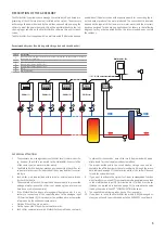
has been designed for double ring applications (as shown in the following
diagram); for any other application than the recommended ones, contact
the company.
RS485
RS485
RS485
RS485
Chiller (1)
Chiller (2)
Chiller (3)
Chiller (n)
5
6
5
6
5
6
5
6
pCOe
Multichiller-Evo
2
1
3
4
Recommended system (double ring with storage tank and circuit breaker)
Index
Component
1
Condensation probe (placed externally for air/water machines; on the condenser return for
the water/water machines)
2
pCOe expansion board (supplied)
3
Circuit breaker temperature probe 1
4
Circuit breaker temperature probe 2
5
Pump
6
Non-return valve
1. The accessory can manage systems with chiller scroll, screw or centrifu-
ge; however, the chillers connected to the Multichiller-Evo must all be
of the same type (air-water or water-water);
2. The Multichiller-Evo does not manage any load outside the chiller; val-
ve pumps or other specific loads cannot in any way be directly control-
led by it;
3. Each chiller must be provided with internal or external pump, driven
by the chiller board;
4. The evaporator of each chiller must have adequate parts to prevent the
passage of water in case the chiller is not operating (non-return valves
have been used in the example);
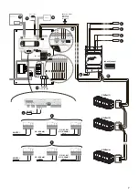
5. If the Multichiller-Eco does not manage multipurpose units, it is ne-
cessary to connect one of the supplied probes to the analogue input
U1 (terminal board J2); this probe must be positioned so as to provide
information on the condenser temperature:
•
Outside if the chillers are air-water;
•
On the source side if the chillers are water-water;
6. Each chiller communicates with Multichiller-Evo via Modbus network;
to achieve this connection, each chiller must be provided with appro-
priate board for serial communication via modbus;
7. The probes positioned in the circuit breaker storage tank and con-
nected to the pCOe board must be set via software (through the proce-
dure indicated on page 27) to determine which of the two will be used
to read the system demand;
8. If you want to activate the system’s set-point compensation function
with climatic curve, use a NTC temperature probe (supplied) connected
to the multifunction input U2 (terminal board J2), which must be set
(through the procedure indicated on page 32) to associate the value
read by the probe to the SET “COMPENSATION function;
9. The supplied temperature probes have a 15 m long cable;
10. If you want to insert the Multichiller-Evo within a BMS-managed sy-
stem, you will need to purchase and install an AER485P1 serial board.
PAY SPECIAL ATTENTION:
230V~50/60Hz
Summary of Contents for Multichiller-Evo
Page 2: ......


