background image

32

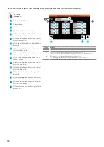
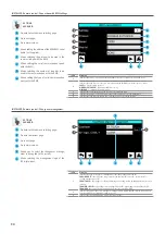
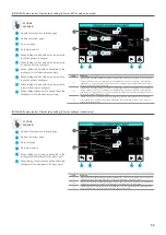
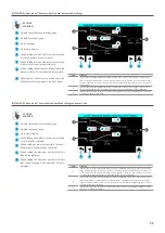
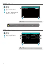
INSTALLER - Remote control - Multi-function input management

A

B

C

Go back to the submenu selecting page;

Index

Meaning

1

Set the function associated with the U2 multi-function input (for the multi-function input to be 
enabled, the ID6 input needs to be open); this function can be:

NONE

 = input disabled;

SET COMPENSATION

 = input used to manage the outdoor air probe (supplied) used for the set 

correction function with climatic curve;

POWER LIMIT

 = input used to calculate the maximum number of chillers to be used depending on 

the type of signal specified at input;

POWER DEMAND

 = input used to calculate the maximum number of chillers to be used depending 

on the type of signal specified at input;

2

Specifies the type of signal at multi-function input; this signal can be:

0-10V

 = a voltage signal from 0 to 10V;

4-20mA

 = a current signal from 4 to 20mA;

NTC

 = a signal from the NTC temperature probe (option to be selected if the supplied probe has 

been connected for compensation with the climatic curve);

3

Set the function associated with the U3 multi-function input (for the multi-function input to be 
enabled, the ID7 input needs to be open); this function can be:

NONE

 = input disabled;

SET COMPENSATION

 = input used to manage the outdoor air probe (supplied) used for the set 

correction function with climatic curve;

POWER LIMIT

 = input used to calculate the maximum number of chillers to be used depending on 

the type of signal specified at input;

POWER DEMAND

 = input used to calculate the maximum number of chillers to be used depending 

on the type of signal specified at input;

4

Specifies the type of signal at multi-function input; this signal can be:

0-10V

 = a voltage signal from 0 to 10V;

4-20mA

 = a current signal from 4 to 20mA;

NTC

 = a signal from the NTC temperature probe (option to be selected if the supplied probe has 

been connected for compensation with the climatic curve);

ACTIONS 

AVAILABLE:

1

A

B

D

2

Go to next page;

Go to alarms menu;

D

E

F

Allows selecting the function to be assigned to 

the system’s multi-function input;
Allows selecting the type of signal applied to the 

system’s multi-function input;

C

E

Go back to previous page;

F

G

3

G

Allows selecting the function to be assigned to 

the recovery’s multi-function input;

4

H

H

Allows selecting the type of signal applied to the 

recovery’s multi-function input;

Summary of Contents for Multichiller-Evo

Page 1: ...5146901_01 1804 User Manual Multichiller Evo Compatible with Modbus protocol Centralised control Touch control EN ...

Page 2: ......
Page 3: ...O5 ANALOGUE INPUTS PAGE 2 23 INSTALLER INPUTS OUTPUTS STATUS OF PCO5 DIGITAL OUTPUTS 24 INSTALLER INPUTS OUTPUTS STATUS OF PCO5 ANALOGUE OU TPUTS 24 INSTALLER INPUTS OUTPUTS STATUS OF PCOE ANALOGUE INPUTS 25 INSTALLER INPUTS OUTPUTS STATUS OF PCOE DIGITAL INPUTS 25 INSTALLER INPUTS OUTPUTS STATUS OF PCOE DIGITAL OUTPUTS 26 INSTALLER INPUTS OUTPUTS STATUS OF PCOE ANALOGUE OUTPUTS 26 THRESHOLD AND T...

Page 4: ...main working setpoint Page 15 Set the BMS parameters Page 30 Switch the unit on or off Page 15 Set the time periods Page 16 Change system language Page 21 REMEMBER THAT The Multichiller Evo accessory is factory set with the data and parameters of the chillers used for the system it is therefore necessary when ordering to specify the number and type of chiller that the accessory will have to manage...

Page 5: ...r Evo does not manage any load outside the chiller val ve pumps or other specific loads cannot in any way be directly control led by it 3 Each chiller must be provided with internal or external pump driven by the chiller board 4 The evaporator of each chiller must have adequate parts to prevent the passage of water in case the chiller is not operating non return valves have been used in the exampl...

Page 6: ...ard refer to the chiller s manual Total maximum length from Multichiller Evo to the last connected chiller for the modbus network 500m 11 12 Multichiller Evo power supply 230V 50 60Hz Use H05V K or N07V K cables with 300 500V insulation minimum section 1 5 mm2 13 pCOe expansion board power supply 24Vac Power the pCOe board from the dedicated transformer On installation a Class II safety transfor m...

Page 7: ...J1 NO1 C1 NC1 J5 NO2 C2 NC2 J6 NO3 C3 NC3 J7 NO4 C4 NC4 J8 J3 J4 Serial Address ID1 ID2 ID3 ID4 IDC1 B1 B2 GND J9 5V Ref Vdc B3 B4 GND J10 5V Ref Vdc G G0 U1 U2 U3 GND VDC V term GND 5 V REF U4 GND U5 GND VG VG0 Y1 Y2 Y3 Y4 ID1 ID2 ID3 J1 J24 J2 J3 J4 d r a c S M B d r a c s u B d l e i F U1 U2 U3 GND VDC U1 U2 U3 GND VDC J2 U2 NTC U1 U2 U3 GND VDC J2 U2 4 20mA 2 wire U1 U2 U3 GND VDC J2 U2 4 20mA...

Page 8: ...entation in 5 languages Material supplied Notes on the serial connection Regardless of the type of power supply or earthing use a shielded three pole cable connected as shown If the network exceeds the 100 m the termination resistor is required 120Ω J26 Fbus2 Multichiller Evo G G0 RS485 Chiller 1 RS485 Chiller n R 120 Ω R 120 Ω Power supply Shield earth connection mode The serial cable shield must...

Page 9: ...trol board and it also allows you to set the connection via BMS set the thresholds and timings in the ignitions view the software information modify the access password and data to be used for the graphics menu ATTENTION for software versions prior to version 1 2 0 the password is 0442 Password 0000 D MANUFACTURER Protected menu not available to the user Protected menu E SYSTEM LAYOUT It allows yo...

Page 10: ...page of the appli cation however please note that if you are entering a sub menu this icon will not be available because replaced by the icon used to go back to the previous menu then simply press the icon of the menu to be accessed for further information on which menus are activated by the various icons refer to the previous page Scrolling to the next or previous page of a menu once in one of th...

Page 11: ...rop down menu grey background the menu will open and you will be able by pressing it to select the option to be set whereas if it is a numeric value after pressing the white area a numeric keypad will appear with which to enter the desired value to complete the entry press the Enter key Certain parameters e g the functioning mode can change status by simply pressing on the coloured areas that iden...

Page 12: ...d outdoors in case of Air water chiller or on the source return in case of Water Water chiller 3 Current temperature value set as work set 4 Current temperature value read by the NTC probe connected on the pCOe board input B1 5 Current temperature value read by the NTC probe connected on the pCOe board input B2 6 Each image displays one of the units currently controlled by the MULTICHILLER EVO acc...

Page 13: ...ning 1 Indicates the current Chiller to which the displayed data refers 2 Indicates the family to which the displayed Chiller belongs 3 Indicates the value read by the high pressure transducer on the selected chiller this data may be repeated if the unit has several circuits 4 Indicates the value read by the low pressure transducer on the selected chiller this data may be repeated if the unit has ...

Page 14: ...ch the displayed data refers this can be On chiller currently operating Off chiller not currently operating Alarm the chiller is in partial alarm so it can provide a reduced power Serious al the chiller is currently locked by a serious alarm offline the serial connection with the chiller is interrupted ACTIONS AVAILABLE A Go back to System layout menu B Go back to previous page C Allows by pressin...

Page 15: ...ed the CLOCK option for system side management C Go to alarm menu D Go to the 2 4 pipe system recovery side settings page only if a multipurpose unit is present E Set the system side management OFF ON SET2 CLOCK F Set the functioning mode before changing the functio ning mode make sure that all system chillers are off G Set the value of the cold set H Set the value of the heat set I Set the value ...

Page 16: ...VAILABLE D E F Select the day of the week to be set Set the start time divided by hours and minutes of the first time period Set the end time divided by hours and minutes of the first time period G Set the action to be performed during the first time period H I Set the start time divided by hours and minutes of the second time period Set the end time divided by hours and minutes of the second time...

Page 17: ...t G Set the value of the recovery side secondary set H Set the value of the differential A C B E F G H 1 D ON OFF Main functioning settings TIME PERIODS sub menu Copy hourly programs function A B C Go back to the On Off menu Go back to previous page Go to alarms menu Index Meaning 1 Indicates the day from which the hourly program will be copied 2 Indicates the day to which the hourly program will ...

Page 18: ... secondary set ACTIONS AVAILABLE D E F Select the day of the week to be set Set the start time divided by hours and minutes of the first time period Set the end time divided by hours and minutes of the first time period G Set the action to be performed during the first time period H I Set the start time divided by hours and minutes of the second time period Set the end time divided by hours and mi...

Page 19: ... D Set the time hours minutes on the touch di splay board E Set the date day month year on the pCO5 board F Set the time hours minutes on the pCO5 board ON OFF Main functioning settings TIME PERIODS sub menu Copy hourly programs function on recovery side if multipurpose units are present A B C Go back to the On Off menu Go back to previous page Go to alarms menu Index Meaning 1 Indicates the day f...

Page 20: ...scroll the chart forward over time F Allows you to zoom out on the chart CHARTS Display charts in real time regarding values read by the 2 4 pipe system recovery side probes visible if multipurpose units are present A B C Open the menu selecting page Go to the relative system side chart Go to alarms menu Index Meaning 1 Indicates today s date 2 Indicates the current time 3 TheY axis indicates the ...

Page 21: ...ace lan guage LANGUAGE Selection of system language A B Open the menu selecting page Go to alarms menu Index Meaning 1 Indicates the actual language set on the system ACTIONS AVAILABLE C Allows selecting the English language D Allows selecting the Italian language A B C D 1 ...

Page 22: ...42 INSTALLER Access password entering A B C Allows entering the numeric value of the password 0442 Allows confirming the entered password Go back to the menu selecting page Index Meaning 1 Indicates today s date 2 Indicates the current time ACTIONS AVAILABLE INSTALLER Sub menu selecting page A B C Open the menu selecting page Go to alarms menu Open the timing and threshold sub menu ACTIONS AVAILAB...

Page 23: ...o to next page Go to alarms menu INSTALLER Inputs Outputs Status of pCO5 analogue inputs page 2 A B C Go back to the submenu selecting page Index Meaning 1 Indicates the actual state of digital input ID1 functioning mode 2 Indicates the actual state of digital input ID2 connected to the system On Off 3 Indicates the actual state of digital input ID3 connected to the recovery side On Off 4 Indicate...

Page 24: ... 5 Not used 6 Not used 7 Not used 8 Not used ACTIONS AVAILABLE 1 A C D 2 3 4 5 6 B 7 8 INSTALLER Inputs Outputs Status of pCO5 analogue outputs A B C Go back to the submenu selecting page Index Meaning 1 Not used 2 Not used 3 Not used 4 Not used ACTIONS AVAILABLE 1 A C D 2 3 4 Go to next page Go to alarms menu B A B C Go back to the submenu selecting page Go back to previous page Go to next page D...

Page 25: ...l temperature value detected by the NTC probe connected to analogue input B3 on the pCOe expansion board 4 Actual temperature value detected by the NTC probe connected to analogue input B4 on the pCOe expansion board ACTIONS AVAILABLE 1 A C D 2 3 4 Go to next page Go to alarms menu B INSTALLER Inputs Outputs Status of pCOe digital inputs A B C Go back to the submenu selecting page Index Meaning 1 ...

Page 26: ... 1 Not used 2 Not used 3 Not used 4 Not used ACTIONS AVAILABLE 1 A C D 2 3 4 Go to next page Go to alarms menu B D Go to alarms menu INSTALLER Inputs Outputs Status of pCOe analogue outputs A B C Go back to the submenu selecting page Index Meaning 1 Not used ACTIONS AVAILABLE 1 A C Go to next page Go to alarms menu B ...

Page 27: ... way the hours worked by each chiller will not be taken into account Optimiser 2 during the Multichiller Evo commissioning the loading is met using the fixed threshold logic then this logic follows the same algorithm as above however in this case the calcu lated combination will operate the selected chillers with the same partialisation steps 2 Indicates whether to use one of the chillers as monit...

Page 28: ...Set the duration of the power demand maintai ning it above the threshold defined in parameter E to enable the ignition of an additional chiller H Set the duration of the power demand maintai ning it below the threshold defined in parameter F to enable the switch off of a chiller INSTALLER Thresholds and timing Optimisation logic settings A B D Go back to the submenu selecting page Index Meaning 1 ...

Page 29: ...gher index if more chillers have the same index the one with the highest number of worked hours will switch off first ACTIONS AVAILABLE A C D Go back to previous page Go to alarms menu Set the cooling priority of the chillers E F B C Go to next page Set the cooling heating priority of the chillers INSTALLER Thresholds and timing Backup chiller settings A B D Go back to the submenu selecting page I...

Page 30: ... speed with the BMS G H Allows selecting the number of stop bits to be used in the communication with the BMS Allows setting the type of serial communication parity with the BMS INSTALLER Remote control Changeover management A B C Go back to the submenu selecting page Index Meaning 1 Indicates the type of changeover management type this management can be COOLING ONLY the chillers do not provide fo...

Page 31: ...put C E Go back to previous page F G 3 G Allows enabling the system s On Off by BMS INSTALLER Remote control Enable On Off from digital input A B C Go back to the submenu selecting page Index Meaning 1 Sets and confirms the units of measurement to use to manage the units 2 Displays the actual set point with the relative unit of measurement applied ACTIONS AVAILABLE 1 A B D 2 Go to next page Go to ...

Page 32: ...ut for the multi function input to be enabled the ID7 input needs to be open this function can be NONE input disabled SET COMPENSATION input used to manage the outdoor air probe supplied used for the set correction function with climatic curve POWER LIMIT input used to calculate the maximum number of chillers to be used depending on the type of signal specified at input POWER DEMAND input used to ...

Page 33: ...mperature to raise the primary cooling set C Go back to previous page 3 G Allows setting the increase to be applied to the cooling set for the indicated temperature G E F L H I H I Allows setting at which outdoor air temperature to use the primary heating set Allows setting at which outdoor air temperature to lower the primary heating set L Allows setting the decrease to be applied to the heating ...

Page 34: ...chillers that can be activated G E F L H I H I Allows setting up to which temperature no chiller will be activated heating Allows setting at which temperature the speci fied number of chillers will be activated L Allows setting the maximum number of chillers that can be activated INSTALLER Remote control Power demand limitation settings U2 set as voltage or current value A B C Go back to the subme...

Page 35: ...aximum of the input signal INSTALLER Remote control Power demand limitation settings on recovery side A B C Go back to the submenu selecting page Index Meaning 1 Indicates the chart representing the power demand or limitation if selected as function on the U3 input with temperature variation according to the temperature read by the NTC probe connected to the U3 input the chart shows the temperatur...

Page 36: ...to the password to access the installer menu Go to alarms menu C ATTENTION Please make a note of any password change in order to avoid possible forgetfulness INSTALLER Info Software versions display A B Go back to the submenu selecting page Index Meaning 1 Indicates the software component versions of the main pCO5 board 2 Indicates the software component versions of the touch screen ACTIONS AVAILA...

Page 37: ...order to use the optimised managements it is necessary to load the specific data of the units on the Multichiller Evo for more information contact the after sales service assistance 2 Indicates the modbus address to be assigned to each chiller 3 Indicates only for the NSM units working in master slave mode the chiller slave 1 address 4 Indicates only for the NSM units working in master slave mode ...

Page 38: ... The address assigned to the pCOe board must match the one set on the same board via dipswitch By default the dips on the board are set to assign the pCOe address 10 however if desired you can modify it with a value between 1 and 15 by properly modifying the dips on the pCOe board ACTIONS AVAILABLE Go to alarms menu B Go back to previous page D Allows selecting the Modbus library to be assig ned t...

Page 39: ...le reading of the various probes specific for the NSM chillers if enabled reading of these probes will be displayed on the monitor pages of each individual chiller page 12 ACTIONS AVAILABLE Go to next page B Go back to previous page D Go to alarms menu E A D C B F G H I L M N O P 1 1 E Enables disables outdoor air probe reading F Enables disables liquid 1 temperature probe re ading G Enables disab...

Page 40: ...Evo page is hidden This is because the WRL unit does not have a modbus system differential If the WRL software is updated then it can be displayed ACTIONS AVAILABLE Go to alarms menu B Go back to previous page D Allows enabling the display of the debug menu 1 D A C B ATTENTION the debug menu is a tool normally used by the technical after sales service assistance to detect any abnormal behaviours E...

Page 41: ... user or installer the parameters contained in this menu are only available to the company s technical after sales service assistance MANUFACTURER Access password entering A B C Allows entering the numeric value of the pas sword Allows confirming the entered password Go back to the menu selecting page ACTIONS AVAILABLE B C A ...

Page 42: ...l ALARMS Displays active alarms A B Open the menu selecting page Go to alarms log Index Meaning 1 Date and time of the alarm 2 Alarm code and description ACTIONS AVAILABLE A B 2 1 ALARMS Displays alarms log A B Open the menu selecting page Update the alarm log Index Meaning 1 Indicates the period to which the displayed alarms refer 2 Date and time of the alarm 3 Alarm code and description 4 Date a...

Page 43: ...ed reboot PLC AL031 Slave1 Chiller1 offline AL032 Slave2 Chiller1 offline AL033 Slave3 Chiller1 offline AL034 Slave1 Chiller2 offline AL035 Slave2 Chiller2 offline AL036 Slave3 Chiller2 offline Index Meaning AL037 Slave1 Chiller3 offline AL038 Slave2 Chiller3 offline AL039 Slave3 Chiller3 offline AL040 Slave1 Chiller4 offline AL041 Slave2 Chiller4 offline AL042 Slave3 Chiller4 offline AL043 Slave1...

Page 44: ...e not binding Aermec reserves the right to make at any time all the modifications deemed necessary for improving the product AERMEC S p A 37040 Bevilacqua VR Italy Via Roma 996 Tel 39 0442 633111 Telefax 0442 93577 39 0442 93566 www aermec com info aermec com ...

Reviews: