The Mpro S & N trip unit types o
ī
er a Short Time Delay func
Ɵ
on
with both a slope se
ƫ
ng and a
Į
xed delay band se
ƫ
ng. The
slope and delay are independently selectable. The slope se
ƫ
ng
consists of three I²t slopes (1, 2, 3) and a
Į
xed delay. The
Į
xed
delay bands have17 constant
Ɵ
me bands.
The minimum and maximum delay
Ɵ
mes are indicated in table
2.5.
The bands of both the slope and
Į
xed delay types are depicted
as Time Current Diagram in appendix 6.1 of this Applica
Ɵ
on
manual.
Installed in the Trip Units types Mpro S and Mpro N the third
SETUP mode display is the adjustable Selec
Ɵ
ve Instantaneous
over current protec
Ɵ
on.
This device causes an undelayed breaker trip when the chosen
current level (Ii) and proper waveform is reached. The pickup
value may be set in steps of 0.5 x the set user current value Ie
from 2.0 xIe to 15 xIe.
(limited to a maximum 13 x Ie on the 6400Atype). The
Instantaneous pickup accuracy is 10%. The Mpro S and Mpro N
trip units have a user-selectable switchable instantaneous over
current , an addi
Ɵ
onal value of OFF appears at the end of the
lis
Ɵ
ng of numerical values. Choose this se
ƫ
ng to disable
instantaneous protec
Ɵ
on.
The bands are depicted as Time Current Diagram
in appendix 6.1 of this Applica
Ɵ
on manual.
2.2.3.2.1
܌ჽ้
STDB
DŽჽڦ܌ୟԍࢺჽ้Dž
2.2.3.3
ስႠຨ้ԍࢺ
(I)
Mpro S
ࢅ
N
! ႙ۉጱྃ੩ഗਏᆶ܌ჽ้ࠀీLjႜၽ୲
ยዃࢅࠦۨჽݔྷยዃăၽ୲ࢅჽ߳ጲ܀૬Ljᅜ
ስăၽ୲ยዃԈઔ!4!߲!
I²
u!ၽ୲DŽ2Ă3Ă4Džࢅ!2!߲
ࠦۨჽăࠦۨჽݔྷᆶ!28!้߲࢛ۨक़ݔྷă
ፌ܌ࢅፌჽ้क़ሞ!3/6!ዐଚă
ၽ୲ࢅࠦۨჽڦݔྷሞԨᆌᆩ֩! 7/2ዐࣼྺ
้क़ۉୁă
ҾጎሞNqsp!T!ࢅ!Nqsp!O!႙ۉጱྃ੩ഗዐLjڼෙ߲!
TFUVQDŽยዃDžఇ๕၂๖ೡྺۙবڦስႠຨ้ࡗ
ۉୁԍࢺă
ٳڟۨڦۉୁप! )Jj*! ࢅړڦհႚᄲ൱้Ljጎዃ
ࣷة݀ுᆶჽ้ڦୟഗཌቄă๔ۯۉୁኵᅜยዃྺ
օ! 1/6! y! ยዃڦᆩࢽۉୁኵ! JfLjݔྷྺ! 3/1! y! Jf!
ڟ!26!y!JfăDŽ7511B!႙ጎዃฉፌٷྺ!24!y!JfDž
ຨ้๔ۯۉୁඓ܈ྺ! 21&ăNqsp! T! ࢅ! Nqsp! O႙
ۉጱྃ੩ഗਏᆶᆩࢽᅜስڦገ࣑ຨ้ࡗۉୁLj
ेڦ! PGGDŽਸDžኵ၄ሞຕኵଚ܋ăስย
ዃ্ᆩຨ้ԍࢺă
Ԩᆌᆩ֩!7/2!ዐॽݔྷࣼྺ้क़ۉୁă
TRIP UNIT
ཌቄڇᇮ
֡ፕ
2
.
2
2.2-03
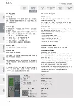
2.2.3.2.1 Short Time Delay STDB
(Delay on delayed Short Circuit Protec
Ɵ
on)
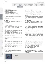
2.2.3.3 Selec
Ɵ
ve Instantaneous Protec
Ɵ
on (I)
!
2.5
ǖ߲߳ۨڦ!
STDB
!ݔྷዐኸۨڪपူ܌้ཌቄ้क़!
-
I²t
!ਸLjڇ࿋ྺࡹ௱!
(²)
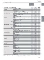
Table 2.5 : Short Time tripping
Ɵ
mes at indicated levels per selected STDB band -I²t OFF. in ms (2)
x Ir
Min
2
3
4
5
6
7
8
9
10
11
12
13
14
15
16
Max
1.5 x ± 10%
ཌቄ
90
100
110
120
170
190
240
270
300
340
400
450
600
700
800
900
1000
փཌቄ
30
40
50
60
110
130
180
210
240
280
340
390
540
640
740
840
940
12 x ± 10%
ཌቄ
90
100
110
120
170
190
240
270
300
340
400
450
600
700
800
900
1000
փཌቄ
30
40
50
60
110
130
180
210
240
280
340
390
540
640
740
840
940
2.6
:
HSIOC
ጎዃ
ยዃኵ
(rms)
Ҿ ጎ ሞ ጲ ۯ ႙ ย Ԣ ዐ ڦ
HSIOC
ጎዃ߁࠵ǖ
ॐڪप4
ME 50M...ME 64M
100.000 A
100.000 A
Table 2.6: HSIOC devices
Set values (rms)
Overview of installed
HSIOC devices in
Automatic ty pes:
Envelope 3
ME 50M...ME 64M
)2*!ॐڪप!4!႙ट၌ྺ!21!y!Jsă)3*!၂๖ྺࢤڦ้क़ޙࢇ!JFD!7158:.2!ࢅ!JFD!71475!Քጚᄲ൱DŽೕ୲ྺ!61!თ࣍ཉॲူDžă
)2*!Po!Fowfmpqf!4!uzqf!mjnjufe!up!21!y!Js/!
)3*!Ujnjoht!jo!Sfe!nffu!uif!sfrvjsfnfout!pg!uif!JFD!7158:.2!boe!JFD!71475!tuboebset!bu!b!gsfrvfodzpg!61!dzdmft/
NF1:ဣଚگუഘୟഗ

