


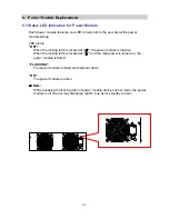

4-8
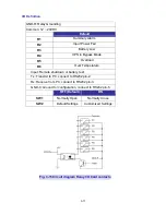
4-6 Wiring
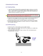
4-6-1 Preparations
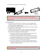
1. The UPS should only be installed by a qualified electrically employed person
2. De-energize all input (AC or DC) or output power of the UPS before installing
cables
or making any electrical connection.
3. Ensure that all cables are correctly marked according to the purpose, as well as
the
polarity, phase and diameter.
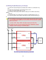
4. If the input/output power of the UPS is WYE-WYE (Y connection),
”Neutral”
and
”Ground”
should not be connected.
If the input power has V
NG
>0, the solution is to install an isolation transformer
before UPS and input power source. Then, connect “
Neutral
” and “
Ground
” of
the UPS together.
5. Make use of suitable conduits and gland to protect I/O wiring according to local
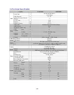
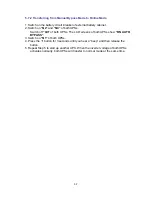
regulations. Refer to Table 4-3.
6. If after the installation many cables are ducted very close together it is
recommended to use cables with isolations made for higher temperature ranges.
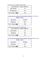
Table 4-3 Input/Output Electrical Data
* Recommended cross section following DIN EN 60269-1 (single wire cables in
free air). Please consider possible deviation due to installed region.
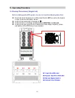
7. Confirm the power phase of L1, L2 and L3.
8. Confirm the polarity of battery cable.
9. Connect the ground of external battery cabinet to UPS’s ground.
10. Connect the UPS’s ground to the protective earth.
UPS
module
quantity
Input
(V)
Output
(V)
Input
Fuse
NH, gL
(A)
Input
Cable
(mm
²
)
Reserve
Fuse
NH, gL
(A)
Reserve
Cable
(mm
²
)
Output
Fuse
NH, gL
(A)
Output
Cable
(mm
²
)
Battery
Fuse
NH, gL
(A)
Battery
Cable
(mm
²
)
1
(20kVA)
230/400 230/400
35
6
50
6
50
6
50
6
2
(40kVA)
230/400 230/400
63
16
75
16
75
16
80
16
3
(60kVA)
230/400 230/400
100
25
125
25
125
25
125
35
4
(80kVA)
230/400 230/400
125
35
150
35
150
35
160
50
5
(100kVA)
230/400 230/400
160
50
200
50
200
50
200
70
6
(120kVA)
230/400 230/400
200
70
250
70
250
70
250
95


