background image

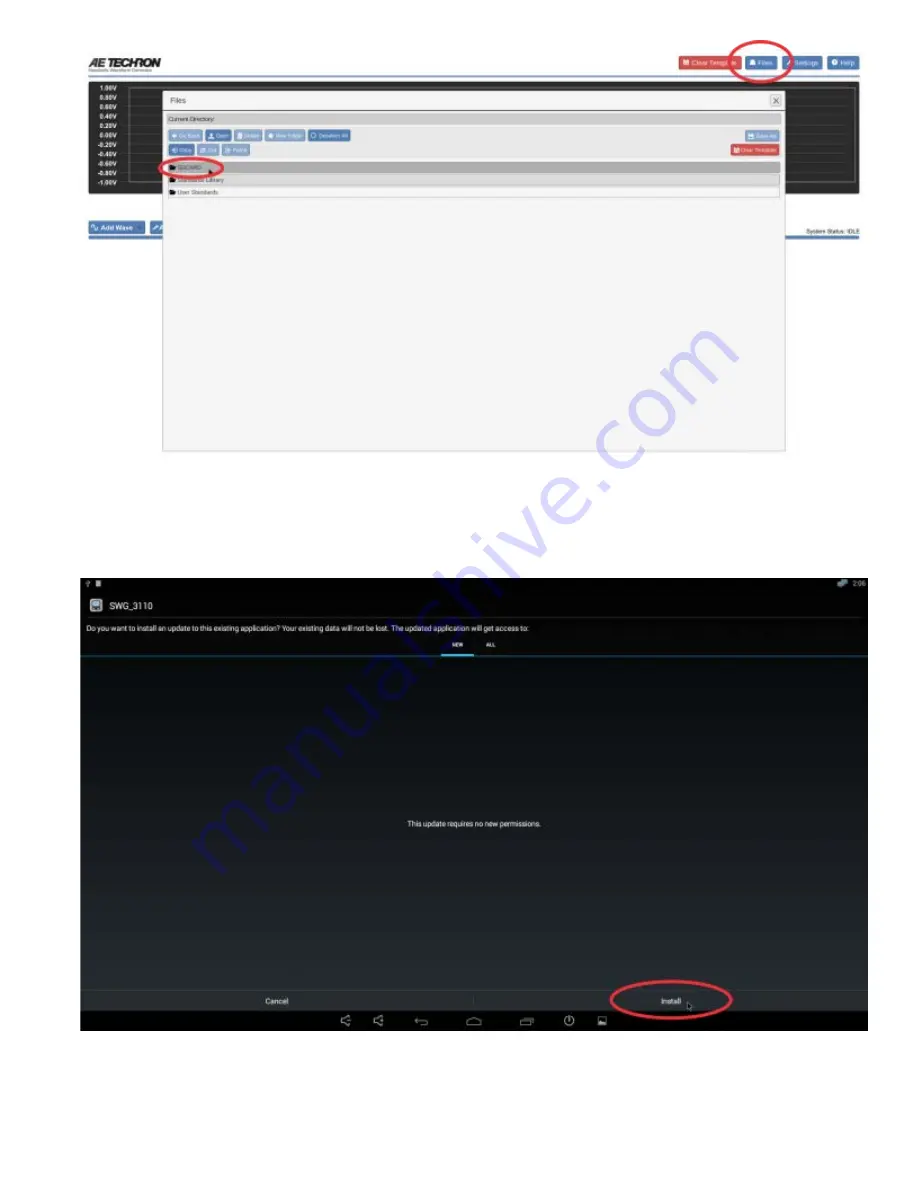
5.  Select and open the .apk file. You will be prompted to approve new permissions (if any). If no new permissions are

required, select the INSTALL button at the bottom right of the screen to start the update process.

6.  The message "App installed" will appear in the window when the update has been successfully performed. Select

the "Done" button to close the dialog box and return to the normal DSR 100-15 interface.

7.  Check the version information displayed on the About Server tab in the Settings window to confirm the update has

Summary of Contents for DSR 100-15

Page 1: ... DSR 100 15 has power in reserve it provides continuous DC power as rated and is able to provide 4X rated power for in rush testing up to 200 mS as is required in DO 160 Section 16 The AE Techron brand is known throughout the world for its robust precision amplifiers and test systems as well as its product service and support Disclaimer Although AE Techron has made substantial effort to ensure the...

Page 2: ...opriate for your application connect fromt he DSR 100 15 front panel positive and negative test supply connectors to the device under test Back Panel Connections A Plug the USB keyboard into the USB port labeled KEYBOARD on the DSR 100 15 back panel B Plug the USB mouse into the USB port labeled MOUSE on the DSR 100 15 back panel C Plug the HDMI to DVI cable into the HDMI port labeled MONITOR on t...

Page 3: ...nd controlled through a network Plug the Ethernet cable to the Ethernet port on the DSR 100 15 back panel labeled NETWORK and then plug the Ethernet cable into a router switch or hub on the network See the topic DSR 100 15 via Network for more information ...

Page 4: ... s power switch last button on the right to turn on the monitor B Depress the DSR 100 15 SYSTEM POWER switch to turn the DSR 100 15 ON C Wait for the DSR 100 15 interface to load loading will take up to 30 seconds See additional topics in this Help system for System Calibration and Basic Operation ...

Page 5: ...out amplification from the Controller s front panel BNC signal output a System Gain of 1 can be used for DSR 100 15 calibration for an expected output of 10Vp 20Vpp Complete the following steps to run the calibration test and adjust the DSR 100 15 s System Gain and DC Offset settings 1 Select the Settings button and then open the System Calibration tab 2 Make sure an estimated gain is entered in t...

Page 6: ...o the DUT load at the Test Supply output 5 Press the Run Calibration Test button to begin the Calibration Test The DSR 100 15 will generate a 1 kHz sine wave signal at the test voltage entered in the Calibration Test Voltage box ...

Page 7: ...ts in the Measured Output and Measured DC Offset boxes on the System Calibration tab The DSR 100 15 Controller will automatically calculated the required Gain and DC Offset adjustments and display them on the Applied Gain Ajustment and Applied DC Offset lines on the System Calibration tab ...

Page 8: ...7 Press the Save button to save the resulting calibration numbers and close the Settings window ...

Page 9: ......

Page 10: ... for more information 1 Select the Settings button and then open the System Calibration tab to set the DSR 100 15 system gain The default setting for a DSR 100 15 system is 20 but this should be calibrated to match your actual system gain If measuring DSR 100 15 Controller output directly without amplification the system gain can be set to 1 for a 10Vp 20Vpp output 2 Use the Files button to load a...

Page 11: ...d Control buttons to select a waveform or control to add to the active test window 4 Select the tab for a waveform or control to open the Properties dialog Edit the properties to create complex waveforms and waveform sequences ...

Page 12: ...5 Segments can be dragged to change their order To remove a segment from the test press the X on the segment s tab ...

Page 13: ...6 When your test sequence is complete press the Arrow button to begin generating signal output from the amplifier ...

Page 14: ...operty settings for that waveform See the individual entries in this Help system for more information about the settings available for each waveform type As you add or adjust settings for the waveform in the Properties tab the visual depiction in the active test window will adjust to reflect the approximate signal being described by the waveform properties Note that time sequences are NOT to scale...

Page 15: ...alibrated and press the blue Calibration button located to the right of the waveform properties The Segment Calibration window will open 2 Connect an oscilloscope to the DUT load at the amplifier output 3 Press the Run Calibration Test button to begin the Calibration Test The DSR 100 15 will continuously generate a waveform with the amplitude and frequency defined in the wave properties 4 Note the...

Page 16: ...able settings for that control opens below the active test display See the individual entries in this Help system for more information about the settings available for each control type To add additional controls to the active test select additional controls from the drop down menu New controls will be added sequentially and will appear to the right of the selected waveform or control in the activ...

Page 17: ...the DSR 100 15 system is currently generating the highlighted segment and the segment is equal to or greater than one second in duration Segments shorter than one second are too short to register as being highlighted STOP When the Stop button is pressed the DSR 100 15 will stop signal generation and the test will reset to the start of the first waveform The system will report its status as Idle Th...

Page 18: ...useful for testing a sequence before generating output ...

Page 19: ...switch as shown below B Power up the DSR 100 15 system and wait for the Controller interface to load this can take up to 30 seconds Press the Settings button to open the Settings window and then select the About Server tab Write down the IP address shown in the IP Address section for later reference and then press the Cancel button to close the Settings window NOTE If the Service Endpoint box is b...

Page 20: ...n the program has loaded the notice Not Connected to DSR Running in Demo Mode Click to Connect will be displayed in the upper left of the window Click the message to open the connection dialog and then type the DSR 100 15 s IP address you wrote down into the IP Address text box Press OK to connect to the remote DSR 100 15 The DSR 100 15 s interface will be displayed on your computer monitor and th...

Page 21: ...NECTING TO THE DSR 100 15 REMOTELY If the DSR 100 15 is disconnected from the network it may be assigned a new IP address when the unit is reconnected to the network To find the new IP go to the DSR 100 15 system reconnect monitor and mouse if necessary and then press the Settings button to open the Settings window Select the About Server tab and review the IP address listing Enter the new IP addr...

Page 22: ... save as a new test file When the test sequence is complete press the Files button to save the swg file in the User Standards directory When working in Demo Mode files saved to the User Standards directory will be saved on your local hard drive in your Documents directory in a sub directory named Demo SWG To transfer the files saved on your local drive to the DSr 100 15 use the provided micro SD c...

Page 23: ...can be retreived from the SD card using the DSR 100 15 locally and can also be transferred using a remote computer connected to the DSR 100 15 via network For more information see the help topic DSR 100 15 via Network ...

Page 24: ... file Save the file on the microSD card with USB adapter that came with your DSR 100 15 unit 2 Remove the back panel of the DSR 100 15 and locate the microSD card slot labeled Memory Card located on the DSR 100 15 Controller s back panel For more information see the topic Accessing the Memory Card Slot 3 Remove the micro SD card from the USB adapter and insert the card into the Memory Card slot Be...

Page 25: ...om right of the screen to start the update process 6 The message App installed will appear in the window when the update has been successfully performed Select the Done button to close the dialog box and return to the normal DSR 100 15 interface 7 Check the version information displayed on the About Server tab in the Settings window to confirm the update has ...

Page 26: ...Follow the instructions provided there for downloading the update file Save the file on your local computer or on a network drive that is accessible to the computer s being updated 2 Locate and open the downloaded exe file via Windows File Explorer You will be prompted to approve the update process Once approved the update process will begin 3 A dialog box will confirm the update has been successf...

Page 27: ...power before beginning this procedure B Using a T 15 Torx driver remove the ten 10 hex head screws from the unit s back panel as shown Being careful not to strain or unplug the attached cables move the back panel aside to gain access to the unit s interior C Locate the microSD card port labled Memory Card which is located near the right side of the DSR 100 15 Controller s back panel as shown ...

Page 28: ...Shutdown Procedure Depress the front panel SYSTEM POWER switch located near the upper right on the front panel to turn the unit OFF ...

Page 29: ...alibration settings for more information see the topic System Calibration The default allowable range is 200Vp with system gain set to 20 When a value outside of the allowable range is entered the input box will turn red and an error message will be displayed Amplitude Sweep Type A Sweep can be Linear Logarithmic or Exponential Choose the desired sweep type from the drop down Frequency The Start F...

Page 30: ...set as the offset amount Duration The Duration property determines how long the waveform will be generated Duration can be defined using the microsecond us millisecond ms second sec minute min or hour hour as the unit of measure When the unit of measure is changed the DSR 100 15 automatically converts the property s value to the new unit of measure The maximum duration of a single segment is 1193 ...

Page 31: ...m Calibration settings for more information see the topic System Calibration The default allowable range is 200Vp with system gain set to 20 When a value outside of the allowable range is entered the input box will turn red and an error message will be displayed Amplitude Sweep Type A Sweep can be Linear Logarithmic or Exponential Choose the desired sweep type from the drop down Frequency The Star...

Page 32: ...set as the offset amount Duration The Duration property determines how long the waveform will be generated Duration can be defined using the microsecond us millisecond ms second sec minute min or hour hour as the unit of measure When the unit of measure is changed the DSR 100 15 automatically converts the property s value to the new unit of measure The maximum duration of a single segment is 1193 ...

Page 33: ...ation The Duration property determines how long the waveform will be generated Duration can be defined using the microsecond us millisecond ms second sec minute min or hour hour as the unit of measure When the unit of measure is changed the DSR 100 15 s Controller automatically converts the property s value to the new unit of measure The maximum duration of a single segment is 1193 hours and the m...

Page 34: ... System Calibration settings for more information see the topic System Calibration The default allowable range is 200Vp with system gain set to 20 When a value outside of the allowable range is entered the input box will turn red and an error message will be displayed Amplitude Sweep Type A Sweep can be Linear Logarithmic or Exponential Choose the desired sweep type from the drop down Frequency Th...

Page 35: ...set as the offset amount Duration The Duration property determines how long the waveform will be generated Duration can be defined using the microsecond us millisecond ms second sec minute min or hour hour as the unit of measure When the unit of measure is changed the DSR 100 15 automatically converts the property s value to the new unit of measure The maximum duration of a single segment is 1193 ...

Page 36: ...ystem Calibration settings for more information see the topic System Calibration The default allowable range is 200Vp with system gain set to 20 When a value outside of the allowable range is entered the input box will turn red and an error message will be displayed Amplitude Sweep Type A Sweep can be Linear Logarithmic or Exponential Choose the desired sweep type from the drop down Frequency The ...

Page 37: ...set as the offset amount Duration The Duration property determines how long the waveform will be generated Duration can be defined using the microsecond us millisecond ms second sec minute min or hour hour as the unit of measure When the unit of measure is changed the DSR 100 15 automatically converts the property s value to the new unit of measure The maximum duration of a single segment is 1193 ...

Page 38: ... System Calibration settings for more information see the topic System Calibration The default allowable range is 200Vp with system gain set to 20 When a value outside of the allowable range is entered the input box will turn red and an error message will be displayed Amplitude Sweep Type A Sweep can be Linear Logarithmic or Exponential Choose the desired sweep type from the drop down Frequency Th...

Page 39: ...set as the offset amount Duration The Duration property determines how long the waveform will be generated Duration can be defined using the microsecond us millisecond ms second sec minute min or hour hour as the unit of measure When the unit of measure is changed the DSR 100 15 automatically converts the property s value to the new unit of measure The maximum duration of a single segment is 1193 ...

Page 40: ...ger Select the GPIO Trigger option if you want an input signal received on one of the three GPIO ports to cause the trigger to be released When GPIO Trigger is selected three GPIO port controls are provided for selection Choose a GPIO port that you have previously designated as a GPIO input during GPIO setup See the help topic Settings for more information After you have selected a GPIO monitor as...

Page 41: ...t property found under the Fixed Loop Start tab To create a fixed loop within a test select the Fixed Loop option from the Add Control drop down menu in the DSR 100 15 s active window Two control icons Fixed Loop Start and Fixed Loop End will be added to the active test sequence Drag the waveform s to be repeated so they are positioned between the Fixed Loop icons Select the Fixed Loop Start tab a...

Page 42: ...waveform will be changed to provide additional drop down lists to be used to assign variables within the Variable Loop Find the waveform property to be varied within the loop and then use the variable assignment drop down to select a letter After variable assignment the input box for that property will be grayed to indicate its status as a variable Check to make sure that the units being used for ...

Page 43: ...to create a 10 loop repeat with starting frequencies from 1000 Hz to 10 000 Hz increasing in 1000 Hz increments and variable A could also be used to create a 10 loop repeat with a duration increasing from 1000 ms on the first loop to 10 000 ms on the final loop Nested Controls All Wave Controls Trigger Fixed Loop Variable Loop Template Playback and GPIO Output can be included within loop controls ...

Page 44: ...p Monitor Window will appear in the DSR 100 15 active window and display the loops contained in the test sequence displaying the number of completed loops out of the total loops required to complete the sequence Note that the Loop Monitor window can be dragged to another location on the screen if desired If the test sequence is stopped the loop monitor count will also be stopped If the test is res...

Page 45: ...drop down menu in the DSR 100 15 s active window A Template icon will be added to the active test sequence Select the Template tab and press the Choose Template button to open the file selection dialog box Locate the swg file for the test desired and then double click on the file name to add it to the Template control Or you can click on the file name to select the swg file and then press the Open...

Page 46: ...ration tab located under Settings See the help topic Settings for more information If a GPIO port has been configured as an input in the GPIO Setup controls that port can be used as a GPIO Trigger only so you must set that Output Port to Ignore no signal on the GPIO Output control properties If one or more GPIO ports has been configured as an output in the GPIO Setup controls you can configure the...

Page 47: ...C power before beginning this procedure B Using a T 15 Torx driver remove the ten 10 hex head screws from the unit s back panel as shown Being careful not to strain or unplug the attached cables move the back panel aside to gain access to the unit s interior C Locate the DB 9 and DB 15 connectors which are located left of center on the DSR 100 15 Controller s back panel as shown ...

Page 48: ...dow Go Back Press the Go Back button to display the files and or folders one level higher in the file system hierarchy Open Press the Open button to open the selected folder or file When a folder is opened the files and or folders one level lower in the file system hierarchy will be shown in the Files window When a file is selected pressing the Open button will cause the file to be loaded into the...

Page 49: ...lso can be used to create a backup of the swg files stored in the DSR 100 15 and to move swg files created on a Windows computer running in Demo Mode to the DSR 100 15 for use See the topic Working in Demo Mode In addition the microSD card is used to update the DSR 100 15 Controller See the topic Updating the DSR 100 15 for more information The SDCARD directory will be visible at the top level of ...

Page 50: ...ied directly to the microprocessor and are not isolated Take care not to exceed maximum ratings as permanent damage can occur We highly recommend optical isolation opto coupler solid state relay etc be used on all GPIO pins before connecting to external equipment Each GPIO port can be configured as an Input or an Output GPIO Input When a GPIO port is configured as an input it can be used in a GPIO...

Page 51: ...ts see the topics Trigger Control or GPIO Output Control Segment Defaults The Segment Defaults tab contains the default settings for SWG waveforms When a new waveform is added into the active window the initial waveform properties will be determined by these default settings To change a default setting select the input box for that setting and then type the new setting into the text box or select ...

Page 52: ...l output to produce the expected signal at the Test Supply output By default the DSR 100 15 is set to a system gain at 20 and DC offset at 0 which are the typical settings for a DSR 100 15 system as configured from the factory For accurate operation the actual gain and offset of your system should be tested by running the Calibration Test See the System Calibration topic in these Help files for mo...

Page 53: ...ins the DSR 100 15 version information for the Software and Firmware It also displays the current IP address for the DSR 100 15 when it is connected to a network This information is automatically displayed and is used for diagnostic purposes ...

Page 54: ...Help The Help button opens this electronic Help system within the DSR 100 15 system You can find additional helpful product information at the AE Techron website at www aetechron com ...

Page 55: ...SR 100 15 system and it will begin generating signal starting with the waveform or control farthest to the left in the active window The DSR 100 15 s System Status should display 1 OF X where X is the total number of waveform segments and controls included in the test sequence Idle When the Stop button is pressed the DSR 100 15 will stop sending signal and the test will reset to the beginning of t...

Page 56: ...you are experiencing is not listed below please contact AE Techron Technical Support at 574 295 9495 for additional help Displayed Messages Indicators Use the front panel indicators to resolve common problems with operation KEY Detail None Detail The front panel power switch controls the power supply to the Controller Make sure this switch in is the ON ...

Page 57: ... the amplifier module Make sure this switch in is the ON position Detail The red switch located on the upper right front panel controls the power supply to the system Make sure this switch is lit Press once to light the switch and turn the power ON Press again to turn the power OFF ...

Page 58: ...ator will light and the amplifier module will be placed in Standby mode when the temperature sensors detect a condition that would damage the system If the Over Temp pulse is extremely short as in the case of defective wiring or switches the Over Temp LED may be lit too briefly to observe To reset after an Over Temp fault has occurred make sure the fans are running and then stop any input signal b...

Page 59: ... Voltage fault condition the AC mains must be brought down to the nominal value If the amplifiermodule does not return to Run mode when the Over Voltage condition has cleared the DSR 100 15 system may require servicing Detail This indicates that an Output Fault condition has occurred and the amplifier module has been placed in Standby mode The Fault indicator will light under two conditions 1 High...

Page 60: ...5 Controller s back panel which can only be accessed by removing the DSR 100 15 back panel See the topic Accessing the Memory Card Slot for more information Be careful when installing the card The card must be inserted with the printed side UP The card also must be inserted in a straight line directly into the card slot If the card is inserted at an angle it may miss the internal card slot and be ...

Page 61: ...e Fault LED is still illuminated and the Fault condition doesn t clear return the amplifier for Factory Service Please see the Factory Service information at the end of this topic Factory Service If the troubleshooting procedures are unsuccessful the DSR 100 15 may need to be returned for Factory Service All units under warranty will be serviced free of charge customer is responsible for one way s...

Page 62: ...g the calibration of the Controller The minimum requirements for calibration documentation are that the instruments used should be able to accurately measure the quantities in Table 1 within the tolerances provided Instruments should bear evidence via a label on the instrument or similar documentation that the measuring instrument is calibrated The table shown below is provided to record the perfo...

Page 63: ... as indicated for each waveform type listed on the far left of Table 1 The duration may be set for several seconds or more depending on the triggering selected The test varies voltage and for alternating waveforms a range of frequencies is given for each voltage level Set up the test waveforms in the User Defined Standards Directory Procedure for Phase Testing A Create a 0 VDC segment of short dur...

Page 64: ...le Start End Amplitude Vp Frequency kHz Measured Frequency kHz Low Limit Vp Measured V High Limit Vp 100 1 4 8 5 3 10 4 8 5 3 100 4 8 5 3 300 3 5 3 6 200 1 9 5 10 5 10 9 5 10 5 20 9 5 10 5 Sawtooth Start End Amplitude Vp Frequency kHz Measured Frequency kHz Low Limit V Measured V High Limit V 100 1 4 8 5 3 10 4 8 5 3 20 4 8 5 3 200 1 9 5 10 5 10 9 5 10 5 20 9 5 10 5 Phase Start End Vp 20 V f 1 kHz...

Page 65: ... See procedure above If you have any questions please contact AE Techron Technical Support at 574 295 9495 ...

Page 66: ...onnector LAN Ethernet connector Output DUT Supply High current connectors Signal Output BNC connector LAN Ethernet connector Waveforms Sine wave sweep ripple cranking DC source triangle wave square wave sawtooth wave Control Functions Trigger fixed loop variable loop template playback Operating Environment Temperature 10 C to 50 C 50 F to 122 F Maximum Output Power de rated above 30 C 86 F Humidit...

Page 67: ...rvice centers or at our factory Expenses in remedying the defect will be borne by AE TECHRON INC including one way surface freight shipping costs within the United States Purchaser must bear the expense of shipping the product between any foreign country and the port of entry in the United States and all taxes duties and other customs fees for such foreign shipments How to Obtain Warranty Service ...

Page 68: ...tion any warranties of merchantability or fitness for a particular purpose No action to enforce this Warranty shall be commenced later than ninety 90 days after expiration of the warranty period AE Techron Inc Custom Service Department 2507 Warren Street Elkhart IN 46516 U S A 1 574 295 9495 ...

Reviews: