AE TECHRON MULTI-AMP CONFIGURATION GUIDE
4
Information subject to change
97-8002465_09-19-14
1.1
Safety First
Throughout these instructions special emphasis is placed on good safety practices. The
WARNING
and
CAUTION
graphics are used to highlight certain topics that require extra precaution.
1.2
Overview
A single AE Techron amplifier can provide continuous output current or voltage only up to a certain level. If
you need increased output above those levels, you can combine multiple amplifiers into a system that can
provide increased voltage or current. Because the internal circuitry of a 2100 or 7000-Series amplifier is not
connected to chassis ground, these
amplifiers are well suited for use in
series or parallel with other like-
model amplifiers within the Series.
Each amplifier added to a Series
multi-amp system will increase the
continuous voltage output, while
each amplifier added to a Parallel
multi-amp system will increase the
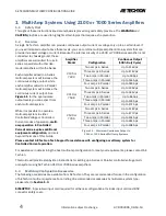
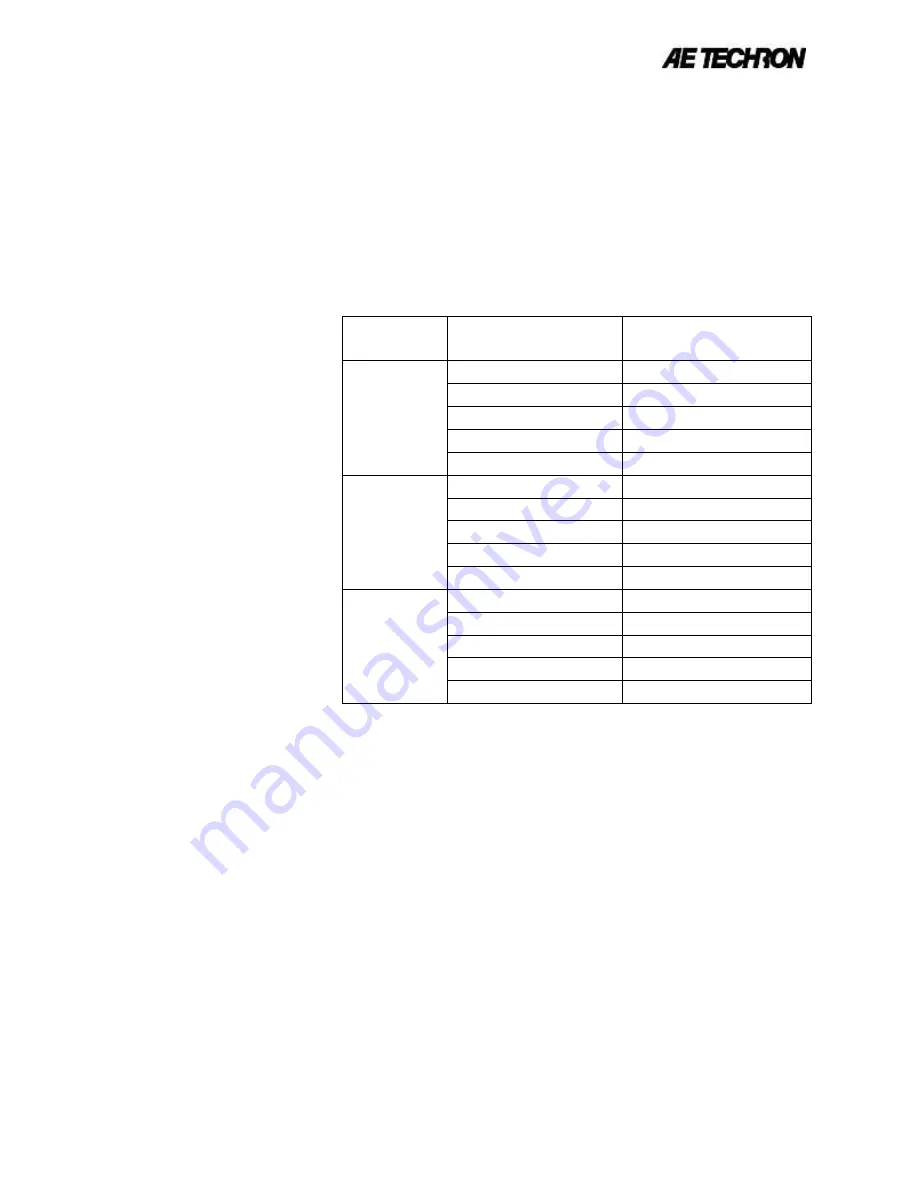
continuous current output. See
Figure 1.1
for the approximate
output levels you can expect from
each multi-amp system.
While it is possible to operate a
multi-amp system in either
Controlled Voltage or Controlled
Current modes of operation
, multi-
amp operation in Controlled
Current mode requires additional
equipment configuration,
and so is
beyond the scope of this Guide.
Please contact AE Techron Tech Support for assistance with configuring a multi-amp system for
Controlled Current operation.
For assistance in determining the best multi-amp configuration to meet your requirements, please contact AE
Techron.
This Guide will provide step-by-step instructions for setting up a Series or Parallel controlled-voltage multi-
amp system using AE Techron 2100 or 7000-Series amplifiers.
1.3
Multi-Amp Configuration Accessories
The following accessories are available from AE Techron. They are recommended for use in the configuration
of AE Techron multi-amp systems. For a listing of recommended accessories by multi-amp system type,
please refer to
Section 1.4.
SIM-OPTOC
– Specialized input card required for all Series configurations. Includes input card and BNC
connector safety cover.
1
Multi-Amp Systems Using 2100 or 7000 Series Amplifiers
Amplifier
Model
Configuration
Continuous Output
(100% Duty Cycle)
2105 or
7224
Two amps in Series
Up to 316 Vpk
Three amps in Series
Up to 474 Vpk
Two amps in Parallel
Up to 90 Apk
Three amps in Parallel
Up to 135 Apk
Four amps in Parallel
Up to 180 Apk
2110 or
7548
Two amps in Series
Up to 390 Vpk
Three amps in Series
Up to 585 Vpk
Two amps in Parallel
Up to 86 Apk
Three amps in Parallel
Up to 129 Apk
Four amps in Parallel
Up to 172 Apk
2120 or
7796
Two amps in Series
Up to 318 Vpk
Three amps in Series
Up to 477 Vpk
Two amps in Parallel
Up to 254 Apk
Three amps in Parallel
Up to 381 Apk
Four amps in Parallel
Up to 508 Apk
Figure 1.1 – Maximum Continuous Output in
2100 or 7000-Series Multi-amp Systems


