AE TECHRON MULTI-AMP CONFIGURATION GUIDE
97-8002465_09-19-14
Information subject to change
29
Appendix C: Building Parallel System Output Cables
The Parallel Wiring Kits available through AE Techron include pre-built cables to be used for Output
connections. This section describes how to build your own output cables, if you so choose.
Select wire appropriate for your application, load and expected output. For
2105 or 7224
Parallel systems,
10 AWG wire will be suitable for most applications. For
2110 or 7548
Parallel systems, 8 AWG wire will
typically be required.
2120 or 7796
Parallel systems with a high-impedance load and continuous output at
less than 60 Arms can typically be wired with 6 AWG wire. However for 7796 systems running high-current,
continuous-duty applications, #4 welding wire may be necessary.
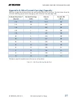
If a jump wire is used to connect from the parallel output cables to the load, it should be capable of carrying
the expected total current output of the system. See
Appendix A: Wire Current-Carrying Capacity
for
assistance in determining the requirements for your system.
IMPORTANT:
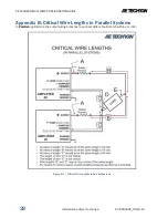
In a paralleled system, it is important
to control the lengths of output cables. Output
cables should be between 2.5 and 4.0 feet in
length, and the lengths of each leg of the output
cables should match within ±1/4-inch. See
Appendix B: Critical Wire Lengths,
for
information on critical cable lengths for paralleled
systems.
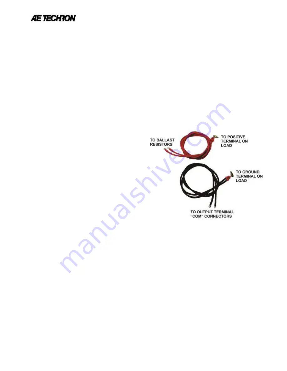
Build two cables for output wiring. Each cable
1.
should contain one leg for each amplifier in
your system. Color-code the cables using RED
for the cable to connect to the positive
terminal of the load; use BLACK for the cable
to connect to the ground terminal of the load.
The wires should be terminated at one end
2.
into a spade lug, ring terminal or other
terminal suitable for the system output and
adaptable to the connectors on the load.
Terminate each of the legs of the RED cable with ring terminal ends to facilitate connection to each
3.
ballast resistor.
The legs of the BLACK cable should be un-terminated to facilitate connection into the amplifier’s barrier
4.
block COM connector.
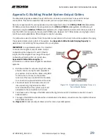
See
Figure C-1
for sample output cables (used for a two-in-parallel system).
Figure C-1 – Output Cables constructed for use in a
Two-in-Parallel System

