advidia VP-16 Series User Manual Download Page 21

20


Figure 4.3.1 User Login


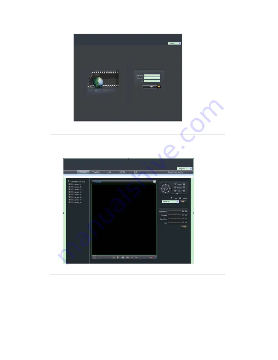
In the preview window as shown in Figure 4.3.2, click the camera list from the site tree to live view the video. The 

right control panel is for PTZ control, and the tool bar at bottom is for  preview, capture, start record, stop record, 

etc. 


Figure 4.3.2 Preview Interface


Click  “Playback”


button  to  enter  the  playback  interface.  Select  the  channel  for  playback  and  search  the  record 

files  by  date  from  the  right  column.  If  corresponding  record  file  is  found,  the  time  bar  will  be  displayed  at  the 

window bottom. Click “Play”


or “Download”


to play or download the selected record file. Refer to Figure 4.3.3. 

Summary of Contents for VP-16 Series

Page 1: ...VP 16 Series Encoder Server USER S MANUAL V1 0 1...

Page 2: ...away from the VP 16 Please check the power supply to avoid damage caused by voltage mismatch Please make sure the VP 16 works in the allowed range of temperature and humidity Please keep the device ho...

Page 3: ...Alarm Output Connections 11 C H A P T E R 3 13 Network Parameters Configuration 13 3 1 Hyper Terminal Setup 14 3 2 Network Configuration by Hyper Terminal 16 C H A P T E R 4 18 Device Configuration 1...

Page 4: ...3 5 1 PPPoE Settings 30 5 2Access by Router 31 Appendix A Specifications 33 Appendix B FAQ 35 Appendix C Glossary 36...

Page 5: ...4 C H A P T E R 1 Introduction...

Page 6: ...g Multiple Recording Periods Configurable Up to 8 recording periods can be configured for each day with different recording type selectable for each recording period Cycle Recording Either cycle recor...

Page 7: ...callup of predefined presets patrols or patterns Alarm Relay Alarm Input Either NO mode or NC mode can be set Four different alarm arming periods are configurable Capabilities of triggering correspond...

Page 8: ...h and view all recorded system logs by date or type as well as export the logs to the text format over network SDK Interface Available with SDK in Windows and Linux operating systems Available with ap...

Page 9: ...8 C H A P T E R 2 Structure...

Page 10: ...ace for connection to audio output device e g loudspeaker etc 5 RS 232 Serial interface for configuration of device s parameters or used as transparent channel 6 POWER Power on off 7 LAN 10 100 1000Mb...

Page 11: ...the connections shown below Alarm input connections for Emerson Alarm Alarm input connections for Normal Alarm 2 3 2 Alarm Output Connections VP 16 supports the open close relay input as the alarm out...

Page 12: ...l can be safely used both in NC and NO methods and it is recommended that they be used within the limit of 12V 1A For external AC input JJl must be open The motherboard provides two jumpers each corre...

Page 13: ...12 C H A P T E R 3 Network Parameters Configuration...

Page 14: ...ect decoder and PC with serial line run Hyper Terminal and modify parameters with serial command Please connect the RS 232 port of decoder directly to the COM port of PC power on the decoder and PC an...

Page 15: ...2 Step4 Serial port setup Set port parameters in COM1 Properties dialogue box as follow Fig 3 1 3 Figure 3 1 3 The parameters should be Bits per second 115200 Data bits 8 Parity None Stop bits 1 Flow...

Page 16: ...mes of all Hyper Terminal are included You can see an icon named as VI here Figure 3 1 5 3 2 Network Configuration by Hyper Terminal Enter Hyper Terminal Click Start Programs Accessories Communication...

Page 17: ...11 255 255 255 0 getPort Get data port of the current video server Command format getPort Enter setPort Get data port of the video server Default port 8000 command format getPort Port No e g setPort 9...

Page 18: ...17 C H A P T E R 4 Device Configuration...

Page 19: ...en the accessories box to take out the disk which provides camera finder software supplied by our corporation The following section describes the configuration of encoder through the software Operatin...

Page 20: ...nPcap is not installed 4 2 Access to Encoder by IE Open IE browser input the IP address of VP 16 e g 192 0 0 64 and then click Enter The system will remind you to install the ActiveX control Click and...

Page 21: ...is for preview capture start record stop record etc Figure 4 3 2 Preview Interface Click Playback button to enter the playback interface Select the channel for playback and search the record files by...

Page 22: ...ure 4 3 4 Log Search Interface Click Config to enter local setting or remote setting interface The local setting interface is used for configuring the saving directories for record files and the remot...

Page 23: ...le of realizing the control of pan tilt unit or speed dome connected as well as performing the pan tilt movement preset calling patrol and other functions of the speed dome either by client software o...

Page 24: ...ddress which must be the same with the configuration in connected pan tilt unit or speed dome Figure 4 4 1 RS485 Settings Enter the Preview interface and click the corresponding channel of the connect...

Page 25: ...24 C H A P T E R 5 Remote Monitoring...

Page 26: ...E Settings Select PPPoE Settings from the Remote Configuration interface and then click the checkbox of Enable PPPoE Enter the user name and password of ADSL and click Save The system will display the...

Page 27: ...der VP 16 Domain Name enter the domain obtained from the DynDNS web site Finally enter the User Name and Password registered in the DynDNS network 5 2 Access by Router Note The following settings are...

Page 28: ...001 and IP is 192 168 1 24 Next enable all or TCP protocols Enable the port map after pressing Save Figure 5 2 3 Set Network Parameters With the settings mentioned above map the router s port 80 and 8...

Page 29: ...p p 1k Voice talk input 1 ch MIC connector Video Audio output Video loop out DB26 connector optional Audio output 1 ch MIC connector Recording resolution VP 16 QCIF CIF 2CIF DCIF 4CIF Frame rate VP 16...

Page 30: ...interface SATA interface 1 1 Alarm in 16 Alarm out 4 Others LED Indicator Ready Tx Rx Link HD Power Channel Status LED Indicators Chassis 1U 19 inch Rear panel provides Reset button Power supply Exter...

Page 31: ...n t I add decoder with software 1 Check the decoder IP 2 Cable is connected 3 User name and password of decoder are correct Why can t I playback the recorded file in VP 16 with decoder 1 Check the VP...

Page 32: ...olution The display resolution refers to the maximum display zone on the screen in certain display mode measured in horizontal and vertical pixels The image resolution describes the detail a digital i...

Reviews: