background image

11

UNO-3272G User Manual

Chapter 2

H

/W Installation

2.2

Jumpers

Configure the UNO-3272G to match the needs of your application by setting jumpers.
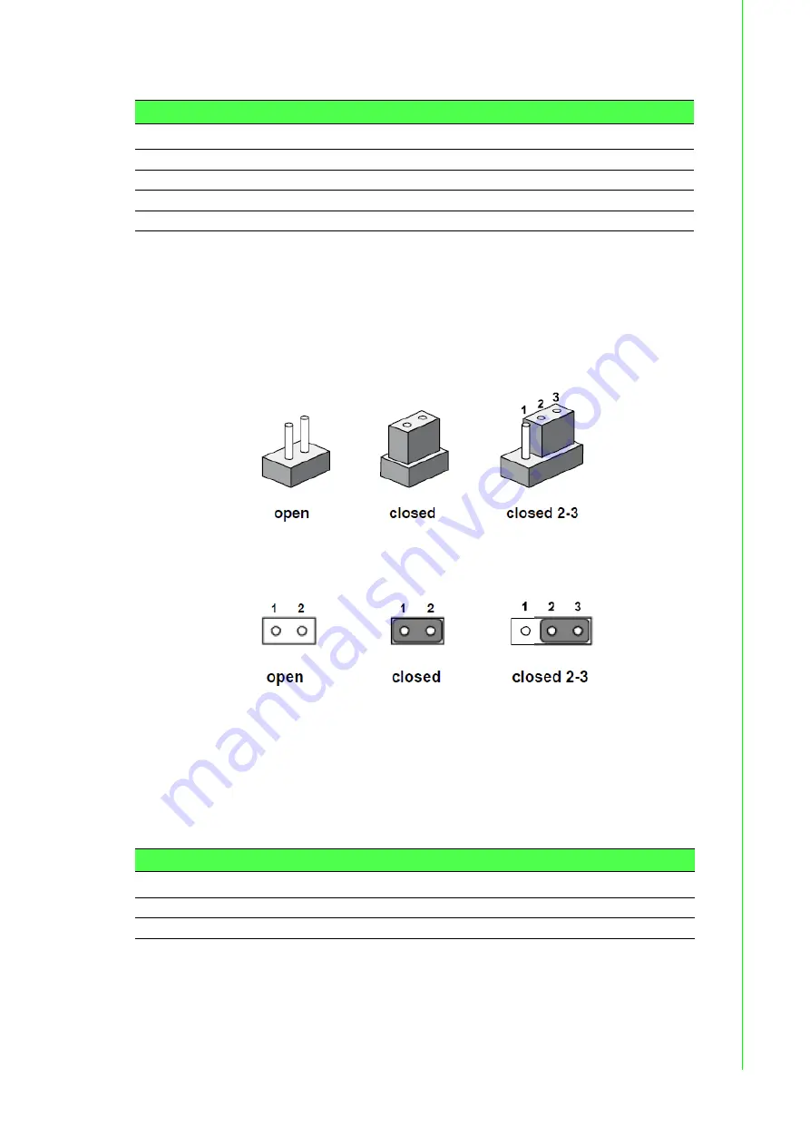
To close a jumper, you connect the pins with the clip. To open a jumper, you remove
the clip. Sometimes a jumper will have three pins, labeled 1, 2 and 3. In this case you
would connect either pins 1 and 2, or 2 and 3.

The jumper settings are schematically depicted in this manual as follows.
 

A pair of needle-nose pliers may be helpful when working with jumpers. If you have
any doubts about the best hardware configuration for your application, contact your
local distributor or sales representative before you make any changes. Generally, you
simply need a standard cable to make most connections.

2.2.1

Jumper list

Table 2.3: COM Connector 

Location

Function

CN2

COM1/COM2

CN3

COM3COM4

CN4

MIC IN

CN6

LINE Out

Table 2.4: Jumper List (motherboard)

Location

Function

CN1

Clear CMOS

CN14

System AT/ATX mode option

Summary of Contents for UNO-3272G Series

Page 1: ...User Manual UNO 3272G Intel Celeron J1900 processors Embedded Automation Computer with PCIe PCI Extension slots...

Page 2: ...is and other Advantech products please visit our websites at http www advantech com For technical support and service please visit our support website at http support advantech com This manual applies...

Page 3: ...nformation readily available 3 If your product is diagnosed as defective obtain an RMA return merchandize authorization number from your dealer This allows us to process your return more quickly 4 Car...

Page 4: ...al attachments Description of your software operating system version application software etc A complete description of the problem The exact wording of any error messages Safety Precaution Static Ele...

Page 5: ...For safety reasons the equipment should be opened only by qualified service personnel 14 If one of the following situations arises get the equipment checked by service personnel The power cord or plug...

Page 6: ...les mises en garde et tous les avertissements sur l quipement doivent tre not s 10 Si l quipement n est pas utilis pendant une longue p riode d branchez le de la source d alimentation pour viter tout...

Page 7: ...vii UNO 3272G User Manual 1 2 3 4 5 6 7 8 9 10 11 12 13 14 15 20 4 60 140 16 17 18 IEC 704 1 1982 70 19 20 IEC 704 1...

Page 8: ...oid damaging hardware or losing data e g There is a danger of a new battery exploding if it is incorrectly installed Do not attempt to recharge force open or heat the battery Replace the battery only...

Page 9: ...e 2 1 Motherboard Connector and jumper locations top side 8 Figure 2 2 Motherboard Connector and jumper locations rear side 9 Table 2 1 Motherboard Connector 9 Figure 2 3 PCIe card connector locations...

Page 10: ...d Digital Output Connection 19 2 3 2 Internal I O Connectors 20 Table 2 16 PCIE Connector Pin Assignments 20 2 4 Installation 20 2 4 1 HDD installation 20 2 4 2 Memory M 2 storage installation 23 2 4...

Page 11: ...Chapter 1 1 Overview This chapter provides an overview of UNO 3272G specifications Sections include Introduction Hardware specification Chassis dimensions Accessories...

Page 12: ...ms including Windows 7 Win dows 10 and Linux users can easily integrate applications on application ready plat forms in order to offer versatile functions for diverse requirements 1 2 Hardware Specifi...

Page 13: ...ace for 3 x USB2 0 port 1 x USB3 0 port Supports high speed full speed and low speed capable Supports legacy keyboard mouse software Power Management 10V 36V DC Input Duel from 4pin plug connector Pow...

Page 14: ...C 10 36VDC 1 5 2 RTC battery BR2032 3 V 190 mAh 1 6 Environment Specification 1 6 1 Operating temperature 20 60 C with 0 7m sec air flow with 1x Industrial SSD without PCI PCIe expan sion boards 1 6 2...

Page 15: ...64 random 5 500 Hz 1 Oct min 1 hr axis x y z 3 axes When system is equipped with 2 5 inch HDD 0 5 Grms IEC 60068 2 64 ran dom 5 500 Hz 1 Oct min 1 hr axis x y z 3 axes 1 6 6 Shock during operation Whe...

Page 16: ...UNO 3272G User Manual 6...

Page 17: ...Chapter 2 2 H W Installation This chapter introduces external IO and the installation of UNO 3272G hardware...

Page 18: ...3272G User Manual 8 2 1 Introduction The following sections show the internal jumper settings and the external connectors and pin assignments Figure 2 1 Motherboard Connector and jumper locations top...

Page 19: ...nction Location Function CN3 LANA USB3 0 2 0 CN16 Internal Power Switch Reset CN4 LANB USB2 0 CN18 M 2 CN5 VGA CN65 Power Input CN7 Internal USB2 0 MPCIE1 Mini PCIe CN8 SATA Power SLOT1 PCIE Slot CN9...

Page 20: ...2G User Manual 10 Figure 2 3 PCIe card connector locations Figure 2 4 COM card connector locations Table 2 2 PCIE Connector Location Function CN1 12V Power Output CN2 5V 12V Power Output CN3 PCIE2 CN4...

Page 21: ...tings are schematically depicted in this manual as follows A pair of needle nose pliers may be helpful when working with jumpers If you have any doubts about the best hardware configuration for your a...

Page 22: ...osed This procedure will reset the CMOS to its default setting 2 2 1 2 System AT ATX mode function option UNO 3272G supports AT or ATX mode and default is ATX module If you want to change to AT mode y...

Page 23: ...communication interface ports Default set ting is RS 232 but this can be modified by BIOS setting You can find detailed setting methods in Chapter 3 Figure 2 6 COM Connector Table 2 5 COM Connector P...

Page 24: ...on MDI 0 corresponds to BI_DB 10BASE T and 100BASE TX In MDI configura tion MDI 0 is used for the transmit pair and in MDIX configuration MDI 0 is used for the receive pair 2 MDI0 3 MDI1 In BASE T Med...

Page 25: ...e USB2 0 interface connectors which give complete Plug Play and hot swapping for up to 127 external devices The USB interface complies with USB XHCI Rev 3 0 Please refer to the table below for pin ass...

Page 26: ...z Figure 2 12 HDMI Connector Table 2 11 VGA Connector Pin Assignments Pin Signal Name Pin Signal Name 1 Red 2 Green 3 Blue 4 NC 5 GND 6 GND 7 GND 8 GND 9 5V 10 GND 11 NC 12 DDC_DAT 13 H SYNC 14 V SYNC...

Page 27: ...button LED indicators UNO 3272G comes with a Power On Off button with LED indicators on the front side to show its On status Green LED and Off Suspend status Yellow LED that sup ports dual function o...

Page 28: ...and DGND Pin 6 9 use DGND The following figure shows how to connect an external input source to the card s isolated inputs Figure 2 14 Isolated DI Dry connection 6 DI0 Isolated digital input 7 DI1 Is...

Page 29: ...voltage source 5 40 V is connected to each isolated output channel IDO and its isolated digital output turns on 200 mA max ch the card s current will sink from the external voltage source The followin...

Page 30: ...UNO 3272G supports 1 HDD SDD installation The following steps demonstrate how to install 2 5 storage 1 Remove 8 screws from top and side cover of UNO Table 2 16 PCIE Connector Pin Assignments CN1 CN2...

Page 31: ...21 UNO 3272G User Manual Chapter 2 H W Installation 2 Remove the 4 screws on rear cover of UNO 3 Take off the HDD SSD tray from rear cover inside...

Page 32: ...UNO 3272G User Manual 22 4 Secure the HDD with 4 pcs reserved screws in the accessory package 5 Slide down the tray and replace all the screws and put the cover back...

Page 33: ...support up to 8GB by adding addi tional 4G Memory UNO 3272G also provides M 2 B key storage with up to 512 GB Following steps demonstrate how to install additional RAM and M 2 Storage 1 Remove the 8...

Page 34: ...steps demonstrate how to install the iDOOR module with the mPCIe card 1 Remove 8 screws from top and side cover of UNO install the mPCIe module as below 2 Remove iDOOR screws on front panel and take...

Page 35: ...ation 2 4 4 DI O card Installation Optional UNO 3272G allows 4 x DI DO by ordering additional DIO cards PN UNO 3000 DIOAE Follow these steps to demonstrate how to install a DI O card 1 Remove the rubb...

Page 36: ...UNO 3272G User Manual 26 2 Fix the DI O card by replacing the 2 screws on accessory package 3 Connect DI O cable as below Motherboard CN13...

Page 37: ...Optional UNO 3272G provides 2 x PCIex1 expansion slots for add on cards Follow the steps for how to install add on cards 1 Remove 8 screws from the top and side cover of UNO as well as the PCI PCIe b...

Page 38: ...6 FAN kit Installation Optional The following steps demonstrate how to install an optional fan kit PN UNO 3000 FANAE 1 Remove 8 screws from the top and side cover of UNO and take out the filter 2 Remo...

Page 39: ...29 UNO 3272G User Manual Chapter 2 H W Installation 3 Fix the fan kit by replacing the 4 screws 4 Connect power cable as below...

Page 40: ...r card change Installation UNO 3272G provides other riser cards 2 x PCI for different applications 1 Pull out the current riser card and remove the copper pillars from the chassis 2 Plug in the new ri...

Page 41: ...ation Optional UNO 3272G supports wall mount and stand mount Optional mounts PN UNO 3000 WMKAE 2 4 8 1 Wall Mounting 1 Remove the screws from UNO chassis then fix the mounting kit on UNO using the sam...

Page 42: ...UNO 3272G User Manual 32 2 4 8 2 Stand Mounting 1 Remove the screws from the UNO chassis then fix the mounting kit on UNO using same screws 2 Install UNO 3272G by replacing the 4 screws...

Page 43: ...Chapter 3 3 AMI BIOS Setup This chapter introduces how to set BIOS configuration data...

Page 44: ...gation of the UNO 3272G setup screens 3 2 Entering Setup Press the Del or Esc key during the Power On Self Test POST process to enter the BIOS setup screen otherwise the system will continue the POST...

Page 45: ...System Date using the Arrow keys Enter new values through the keyboard Press the Tab key or the Arrow keys to move between fields The date must be entered in MM DD YY format The time must be entered...

Page 46: ...Trusted Computing Security Device Support This item allows users to enable or disable Security Device Support 3 2 2 2 ACPI Settings Enable ACPI Auto Configuration This item allows users to enable or...

Page 47: ...or disable Hibernation ACPI Sleep State This item allows users to set ACPI mode S3 Suspend to RAM or to Disable ACPI Sleep State Lock Legacy Resources This item allows users to enable or disable Lock...

Page 48: ...Manual 38 Serial Port 1 Configuration Serial Port This item allows users to enable or disable for Serial Port Change Settings This item allows users to Change Settings of Serial Ports The default set...

Page 49: ...efault setting is RS232 Serial Port 2 Configuration Serial Port This item allows users to enable or disable for Serial Port Change Settings This item allows users to change settings of serial ports Th...

Page 50: ...erial Port Change Settings This item allows users to Change Settings of Serial Ports The default setting is Auto Serial Port 4 Configuration Serial Port This item allows users to enable or disable for...

Page 51: ...3 2 2 4 Embedded Controller Configuration iManager WatchDog IRQ This item allows users to enable or disable for iManager WatchDog IRQ 3 2 2 5 S5 RTC Wake Settings Wake system from S5 This item allows...

Page 52: ...3 2 2 6 CPU Configuration Execute Disable Bit This item allows users to enable or disable for Execute Disable Bit Intel Virtualization Technology This item allows users to enable or disable for Intel...

Page 53: ...al Chapter 3 AMI BIOS Setup 3 2 2 7 IDE Configuration 3 2 2 8 Miscellaneous Configuration OS Selection This items allow user to set the OS mode Win 8 x or Win 7 or WinCE 7 If user installs Win 10 or L...

Page 54: ...UNO 3272G User Manual 44 3 2 2 9 LAN Controller LAN Controller This items allowed user to enable or disable for wake on LAN function 3 2 2 10 Network Stack Configuration...

Page 55: ...r Keep Current for Option ROM Messages Boot option filter This item allows users to set UEFI and Legacy or Legacy only or UEFI only for Boot option filter For using Legacy PXE function please set to U...

Page 56: ...torage Driver Support This item allows users to enable or disable USB Mass Storage Driver Support USB transfer Time out This item allows users to set different time mode for USB transfer Time out Devi...

Page 57: ...47 UNO 3272G User Manual Chapter 3 AMI BIOS Setup 3 2 3 Chipset...

Page 58: ...UNO 3272G User Manual 48 3 2 3 1 USB Configuration USB Per port control This item allows users to enable or disable for USB Per port control...

Page 59: ...49 UNO 3272G User Manual Chapter 3 AMI BIOS Setup 3 2 3 2 PCI Express Configuration 3 2 4 Security Set Admin Password This item allows users to set Administrator Password if desired...

Page 60: ...ctivation kay 65535 0xFFFF means indefinite waiting Bootup NumLock State This item allows users to set Bootup NumLock State either On or Off Quiet Boot This item allows users to disable or enable Quie...

Page 61: ...3272G User Manual Chapter 3 AMI BIOS Setup 3 2 6 Save Exit Save Changes and Exit This item allows users to Save Changes and Exit Discard Changes and Exit This item allows users to Discard Changes and...

Page 62: ...ave Changes Discard Changes This item allows users to Discard Changes Restore Defaults This item allows users to restore factory defaults Save as User Defaults This item allows users to Save as User D...

Page 63: ...53 UNO 3272G User Manual Chapter 3 AMI BIOS Setup...

Page 64: ...tions are subject to change without notice No part of this publication may be reproduced in any form or by any means electronic photocopying recording or otherwise without prior written permis sion of...

Reviews: