


PCI/ PCI Express-Communication
User Manual
32
receive data later. Another port, which operates as passive loopback, will retransmit
any received data on the Rx line and then send these data onto the Tx line. These
two modes will form a logical loop and help to verify the integrity of data transmitted
over the communication link.
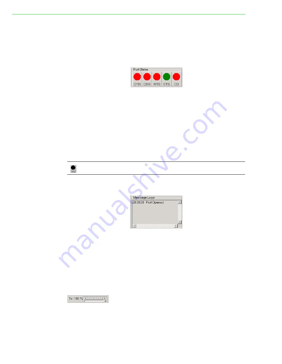
4.3.4
Port Status
DTR (data-terminal-ready)
DSR (data-set-ready)
RTS (request-to-send)
CTS (clear-to-send)
CD (carrier-detect)
For RS-232 specifications, DTR and RTS are for output signals and can be toggled
on and off by double-clicking the labels (such as DTR, DSR, RTS, CTS, CD) under
the red/green marks. However, if you are using RTS/CTS for flow control to run the
test, you will see the RTS mark appear in black. This indicates that the RTS can no
longer be toggled on/ off since it is controlled by driver itself.
4.3.5
Message Logo
On the Message Logo area, you can see the relevant messages about the port(s)
you have selected.
For information about specific messages in this area, please refer to Section 4.5,
Messages on the Status Bar and Message Logo area.
4.3.6
Tx Slide Bar
The Tx Slide Bar allows you to control the overall system loading. You can adjust the
transmission rate of your port(s) from 0% to 100%. Just drag the slide button along
the track to adjust the transmission rate.
4.3.7
Performance Listing Area
On the performance listing area, you can see the relevant information, such as Rx
Length (received packet byte length), Bytes/Sec (transmission rate) and Last Abnor-
mal Status of each port running a test.
A black mark represents that the function is controlled by the driver itself and there-
fore not controllable by software.
Summary of Contents for PCI-1602UP
Page 1: ...User Manual PCI PCI Express COMM Series User Manual Industrial Serial Communication Cards ...
Page 10: ...PCI PCI Express Communication User Manual x ...
Page 11: ...Chapter 1 1 Introduction ...
Page 18: ...PCI PCI Express Communication User Manual 8 ...
Page 19: ...Chapter 2 2 Hardware Configuration ...
Page 33: ...Chapter 3 3 Driver Setup Installation ...
Page 38: ...PCI PCI Express Communication User Manual 28 ...
Page 39: ...Chapter 4 4 ICOM Tools ...
Page 43: ...33PCI PCI Express Communication User Manual Chapter 4 ICOM Tools ...
Page 49: ...Chapter 5 5 Pin Assignments and Wiring ...
Page 63: ...Appendix A A Scale of Connectors ...
Page 66: ...PCI PCI Express Communication User Manual 56 Figure A 5 DB62 Female ...
Page 67: ...57PCI PCI Express Communication User Manual Appendix A Scale of Connectors ...


