Advantech PCI-1220U User Manual Download Page 38

PCI-1220U User Manual

32

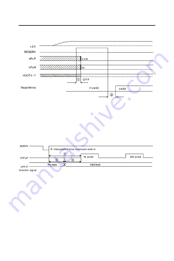
3.15  I/O Signal Timing

3.15.1 Power On RESET

Figure 3.21: Timing Diagram of Power On Reset

•  Output pulses (nP ± P, nP ± N) for drive control and general purpose 

output signals (nOUT0 ~ 3) for I/O control will be determined after 250 
nsec from power on reset.

•  User can access PCI-1220U only after 500 nsec from power-on reset.

3.15.2 Individual Axis Driving

Figure 3.22: Individual Axis Driving

•  The maximum time to output command pulse after first pulse command 

is about 650nsec.

•  When pulse/direction mode, the direction signal will valid after 275 

nsec and pulse output will vaild after 375 nsec after direction signal.

Summary of Contents for PCI-1220U

Page 1: ...PCI 1220U 2 axis Universal PCI Stepping Pulse type Servo Motor Control Card User Manual...

Page 2: ...ts use nor for any infringements of the rights of third parties which may result from its use Acknowledgments PC LabCard is a trademark of Advantech Co Ltd IBM and PC are trademarks of International B...

Page 3: ...lacement materials service time and freight Please consult your dealer for more details If you think you have a defective product follow these steps 1 Collect all the information about the problem enc...

Page 4: ...e problem The exact wording of any error messages Packing List Before setting up the system check that the items listed below are included and in good condition If any item does not accord with the ta...

Page 5: ...ace 18 3 4 General Purposed Output 19 Figure 3 6 General Purpose Output 19 3 5 Over Traveling Limit Switch Input 19 Figure 3 7 Movement Limit Input Signals 20 Figure 3 8 Photo Sensor in the Limit Inpu...

Page 6: ...Input 33 Figure 3 25 Timing Diagram of Up Down Pulse Input 33 3 15 5 Instantaneous Stop Timing 34 Figure 3 26 External Instantaneous Stop Signal 34 Figure 3 27 Instantaneous Stop Instruction 34 3 15...

Page 7: ...2 CHAPTER 1 Introduction This chapter introduces PCI 1220U and lists features and specifications...

Page 8: ...amming load Moreover through a free bundled motion utility you can complete con figuration and diagnosis easily 1 1 Features PCI 1220U provides users with the most requested motor control func tions a...

Page 9: ...ng and circular arc interpolation control The interpolation speed range is from 1 PPS to 4 MPPS Powerful Position Management Function Each axis is equipped with a 32 bit logical position counter and a...

Page 10: ...e driving and continuous driving can be also performed through the external signals This function is used for JOG or teaching modes and will share the CPU load Input Output Signal Each axis has 2 poin...

Page 11: ...ing equipment Other stepping pulse type servo motor applications 1 3 Installation Guide Before you install your PCI 1220U card please make sure you have the following necessary components PCI 1220U Mo...

Page 12: ...PCI 1220U card to provide higher resistance to noise To achieve a better signal quality the signal wires are twisted in such away as to form a twisted pair cable reducing cross talk and noise from ot...

Page 13: ...12202 CHAPTER 2 Installation This chapter gives users a package item checklist proper instructions about unpacking and step by step procedures for both driver and card installation...

Page 14: ...arge static electricity accumulated on your body Or one can also use a grounding strap Touch the antistatic bag to a metal part of your computer chassis before opening the bag Take hold of the card on...

Page 15: ...r and any accessories connected to the computer Warning TURN OFF your computer power supply whenever you install or remove any card or connect and disconnect cables 2 Disconnect the power cord and any...

Page 16: ...PCI 1220U User Manual 10...

Page 17: ...2 CHAPTER 3 Signal Connections This chapter provides useful informa tion about how to connect input and output signals to the PCI 1220U via the I O connector...

Page 18: ...ease refer to Section 3 4 Output Pulse Definition and Section 3 11 Emergency Stop Input for more information about JP1 4 and JP5 config urations BoardID Switch PCI 1220U has have a built in DIP switch...

Page 19: ...13 Chapter 3 Figure 3 1 I O Connector Pin Assignments...

Page 20: ...ALARM Input Servo Error at X axis XECAP Input Encoder Phase A at X axis XECAN Input Encoder Phase A at X axis XECBP Input Encoder Phase B at X axis XECBN Input Encoder Phase B at X axis XEZ Input Enco...

Page 21: ...of X axis XP P GND Output Output pulse CCW DIR of X axis XP N GND Output Output pulse CCW DIR of X axis GND Ground YOUT0 GND Output General Output at Y axis CMP YOUT1 GND Output General Output at Y ax...

Page 22: ...nt bit LSB of Board ID ID3 the most significant bit MSB of Board ID Table 3 2 BoardID register SW1 Board ID register Base Add 12h 3 2 1 0 Abbreviation BDID3 BDID2 BDID1 BDID Table 3 3 BoardID setting...

Page 23: ...mode by writing specified command system register Figure 3 3 Output Signal Loop for Drive Pulses From the circuit shown above Figure 3 3 the default output mode is dif ferential output For single ende...

Page 24: ...PCI 1220U User Manual 18 Figure 3 4 Photo Coupler Input Interface Figure 3 5 Line Driver Input Interface...

Page 25: ...r output during driving 3 5 Over Traveling Limit Switch Input Note When the axis axes is are about to stop in the decelera tion stage the axis axes will not stop totally but keep moving at a very low...

Page 26: ...evel This enables the over traveling function if the desired level of nLMTP is set to low Figure 3 7 Movement Limit Input Signals The response time of this circuit should take about 0 2 0 4 msec becau...

Page 27: ...is low Furthermore these input signals can be used as general purposed input because user can get the level by reading the input register status RR4 RR5 Figure 3 9 Deceleration Instantaneous Stop Inpu...

Page 28: ...bnormal condition they active this signal to note PCI 1220U to stop output pulses When enable the nALARM func tion of PCI 1220U the D14 bit of RR2 will set to 1 after nALARM active If PCI 1220U is dri...

Page 29: ...ble after setting the input pule mode nIN0P N is used for encoder phase Z signal feedback and also can be used as general purposed input or instantaneous stop input Figure 3 11 Circuit Diagram of Enco...

Page 30: ...xample of the connection for encoder with differential output linear driver Figure 3 12 Differential output Line Driver The following figure is an example of connection for the encoder with open colle...

Page 31: ...orre sponding to the Continuous Output Mode and in Hand wheel mode it is corresponding to the Fixed Pulse Output Mode These functions are progressed without CPU involved on host PC When the input sign...

Page 32: ...cuitry should take about 0 25 msec because of the delay of photo coupled and RC filter 3 11 External Power Input VEX External power is necessary for all input signals of each axis Please apply DC12 24...

Page 33: ...s the interrupt structure of the PCI 1220U We suggest users who want to program their own interrupt service routine ISR should follow the procedures Step 1 When interrupt occurs Hardware Step 2 Progra...

Page 34: ...to UPK step drive manufactured by ORIENTAL company Note JP1 4 of PCI 1220U are set to 5V output side 5V output for output terminals XP P and XP P Setting JP1 4 as single ended output will output 5V o...

Page 35: ...differential pulse output of PCI 1220U is connected to CW CCW input of UPK drive XOUT0 can control UPK drive to hold by setting D8 of WR3 TIMING and Over HEAT signals can be read back by reading RR4 5...

Page 36: ...e of PCI 1220U connected to MINAS X series AC servo motor drive Figure 3 20 MINAS X Series AC Servo Motor Drive Note The servo drive must be set in pulse control drive mode and the type of pulse input...

Page 37: ...ed pair wires as the analog input cable This type of cable has its signal wires twisted together and shielded with a metal mesh The metal mesh should only be connected to one point at the signal sourc...

Page 38: ...ol will be determined after 250 nsec from power on reset User can access PCI 1220U only after 500 nsec from power on reset 3 15 2 Individual Axis Driving Figure 3 22 Individual Axis Driving The maximu...

Page 39: ...gnal nP P is valid in 125 nsec of high level pulse signal 3 15 4 Input Pulse Timing Quadrature Pulse of Encoder Input Figure 3 24 Quadrature Pulse of Encoder Input The minimum difference time between...

Page 40: ...on When the Stop instruction is issued during driving at most one pulse will be output and then stopped 3 15 6 Deceleration Stop Timing External Deceleration Stop Signal Figure 3 28 External Decelerat...

Page 41: ...with JP6 you can choose the XOUT0 pin as original design as PCI 1220U or TTL level output While the JP6 is in CMP position the output of XOUT0 is XOUT0 XOUT1 With this special design you can get the...

Page 42: ...PCI 1220U User Manual 36...

Page 43: ...2 APPENDIX A Specifications...

Page 44: ...N nP P N Range 8 388 608 8 388 607 Precision 0 1 Change of Acceleration for S curve 954 31 25 x 109 PPS sec2 Acceleration Deceleration 125 500 x 106 PPS sec Initial Velocity 1 PPS 4 MPPS Drive Speed...

Page 45: ...rt dry wet contact Logic 0 21 24 VDC open dry contact Logic 1 0 16 VDC closed dry contact Protection 2 500 VDC photo coupler isola tion General Purpose Output Output Signal nOUT0 3 Output Voltage Open...

Page 46: ...Isolation Protection Position Counter Range of Command Position Counter for output pulse 2 147 438 648 2 147 438 647 Range of Actual Position Counter for input pulse 2 147 438 648 2 147 438 647 Compar...

Page 47: ...5 x 100 mm 6 9 x 3 9 Power Consumption Typical 300 mA 5 V Max 600 mA 5 V External Power Voltage DC 12 24 V Temperature Operating 0 60 C 32 140 F refer to IEC 68 2 1 2 Storage 20 85 C 4 185 F Relative...

Page 48: ...PCI 1220U User Manual 42...

Page 49: ...2 APPENDIX B Block Diagram...

Page 50: ...PCI 1220U User Manual 44 Appendix B Block Diagram...

Page 51: ...2 APPENDIX C Wiring with Third Party Motor Drivers...

Page 52: ...PCI 1220U User Manual 46 Appendix C Wiring with Third Party Motor Drivers Figure C 1 Mitsubishi MR J2S Series Motor Driver...

Page 53: ...47 Chapter C Figure C 2 Oriental LIMO EZMC Motor Driver...

Page 54: ...PCI 1220U User Manual 48 Figure C 3 Panasonic MINAS A Series Motor Driver...

Page 55: ...49 Chapter C Figure C 4 Yaskawa SGDM Series Motor Driver...

Page 56: ...PCI 1220U User Manual 50...

Reviews: