background image

IPPC-6172A User Manual

26

5.3

Advanced BIOS Setup

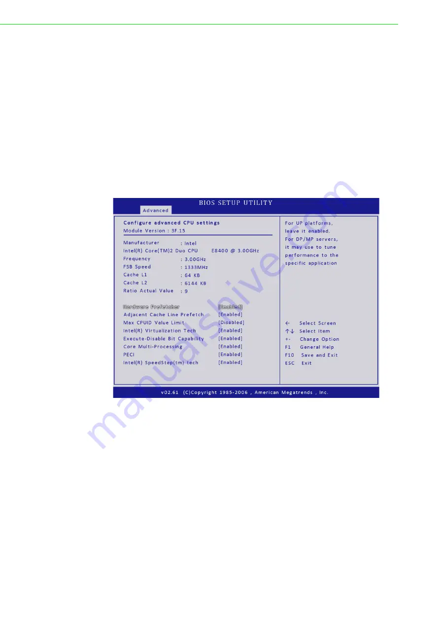
Select the Advanced tab from the setup screen to enter the Advanced BIOS Setup
screen. You can select any of the items in the left frame of the screen, such as Supe-
rIO Configuration, to go to the sub menu for that item. You can display an Advanced
BIOS Setup option by highlighting it using the <Arrow> keys. All Advanced BIOS
Setup options are described in this section. The Advanced BIOS Setup screen is
shown below. The sub menus are described on the following pages.

CPU Configuration Setting

You can use this screen to select options for the CPU Configuration Settings. Use the
up and down <Arrow> keys to select an item. Use the <Plus> and <Minus> keys to
change the value of the selected option. A description of the selected item appears
on the right side of the screen. The settings are described on the following pages.

Hardware Prefetcher
The choices of Hardware Prefetcher which prefetchs data from memory to L2 cache
are Disabled, and Enabled.

Adjacent Cache Line Prefetch

The choices of Adjacement Cache Line Prefetch which automatically fetches an
extra 64-byte cache line are Enabled, Disabled.

Max CPUID Value Limit

The choices of Max CPUID Value Limit are Disabled, and Enabled.

Summary of Contents for IPPC-6172A Series

Page 1: ...User Manual IPPC 6172A Series 17 SXGA TFT LCD Core 2 Quad Core 2 Duo Industrial Panel PC with 2 x PCI Slots...

Page 2: ...ion Advantech assumes no liability under the terms of this warranty as a consequence of such events Because of Advantech s high quality control standards and rigorous testing most of our customers nev...

Page 3: ...can radiate radio frequency energy and if not installed and used in accordance with the instruction manual may cause harmful interference to radio communications Opera tion of this equipment in a res...

Page 4: ...pour any liquid into an opening This may cause fire or electrical shock 13 Never open the equipment For safety reasons the equipment should be opened only by qualified service personnel 14 If one of...

Page 5: ...ng SDRAM 9 2 3 Installing a CPU 10 2 4 Installing a 2 5 SATA HDD 12 2 5 Installing Add on Cards 12 2 5 1 Add on Cards Support 12 2 5 2 Installing Add on Cards 12 2 6 Mounting Instructions 14 2 6 1 Pan...

Page 6: ...s 39 5 5 Boot Setting Configuration 41 5 6 Security Setup 44 5 7 Chipset Setup 45 5 7 1 North Bridge Configuration 45 5 7 2 South Bridge Configuration 47 5 8 Exit Menu 48 Appendix A I O Connector Pin...

Page 7: ...Chapter 1 1 General Information...

Page 8: ...firm solid structure The front panel is made of sturdy aluminum and has strengthened glass It is shock resistant and complies with NEMA4 IP65 Easy Maintenance The rear cover with gull open design abo...

Page 9: ...5 South Bridge Intel ICH10D0 Chipset Intel Q45 GMCH ICH10D0 2nd Level Cache Depends on CPU from 2MB to 12MB RAM Two DDR3 240pin slots up to 4GB 1066 1333 MHz SDRAM NON ECC NON REG Serial Ports 2 x RS...

Page 10: ...espan 36 million writing rate is 250g at 2 times s Light Transmission 80 Controller RS 232 interface COM3 Power Consumption 5 5 V 20 mA Software Drivers Supports Windows 7 Windows XP 1 2 7 Environment...

Page 11: ...6 00 0 24 26 00 1 02 26 00 1 02 97 00 3 82 97 00 3 82 112 20 4 42 112 20 4 42 450 97 17 75 450 97 17 75 335 97 13 23 335 97 13 23 266 70 10 50 266 70 10 50 40 30 1 59 40 30 1 59 464 82 18 30 464 82 1...

Page 12: ...IPPC 6172A User Manual 6...

Page 13: ...Chapter 2 2 System Setup...

Page 14: ...or mouse Follow these instructions 1 Make sure the panel PC and any other peripherial devices you mayhave con nected to the panel PC are turned off 2 Attach the interface cable of the serial device t...

Page 15: ...out jack is connected to exter nal audio devices Line in Input audio from an external CD player or radio 1 Connect the audio device to the system 2 Install the driver before you use the device 2 1 6 E...

Page 16: ...owhead printed on the motherboard points to the end of the lever 4 Slide the CPU in gently It should insert easily If not pull the lever up a little more and make sure the pins of the CPU correspond w...

Page 17: ...11 IPPC 6172A User Manual Chapter 2 System Setup...

Page 18: ...four screws and take off HDD bracket 3 Insert the HDD into the bracket see figure 4 Put the HDD bracket into the Chassis and fasten the four screws 5 Then attach the HDD flat cable and power cable 6...

Page 19: ...CI riser card by loosing the 2 screws which fix the card to the bracket Then find the PCIe riser card from the accessory box and fix it to the bracket with 2 screws 3 Replace the back cover and fix it...

Page 20: ...mounting brackets out of the accessory box 2 Attach the four mounting brackets by inserting the screws into the keyhole slots on the cover of the monitor 3 Use the screws to secure the brackets to the...

Page 21: ...Chapter 3 3 Jumper Settings Connectors...

Page 22: ...imes a jumper will have three pins labeled 1 2 and 3 In this case you connect either pins 1 and 2 or 2 and 3 The jumper settings are schematically depicted in this manual as follows A pair of needle n...

Page 23: ...N5 Touchscreen WaferBOX 2 0mm 9P CN6 CN7 USB Port4 Port5 WaferBOX 2 54mm 5P CN9 CN10 CN11 CN12 SATA POWER PORT WaferBOX 2 54mm 8P CN18 PANEL HEADER WaferBOX 2 0mm 9P KBMS1 PS2 KEYBOARD MOUSE COMD1 COM...

Page 24: ...cedures below to clear the CMOS 1 Turn off the system 2 Remove the Jumper CLRTC1 1 2 3 Close jumper CLRTC1 2 3 4 Remove the Jumper CLRTC1 2 3 5 Close jumper CLRTC1 1 2 6 Turn on the system The CMOS is...

Page 25: ...Chapter 4 4 Intel Chipset...

Page 26: ...the ReadMe txt file on the CD ROM Intel Chipset Software Installation Utility Path INF Available for the OS s below Microsoft Windows 7 Microsoft Windows XP VGA Drivers Intel R Graphics Driver Path V...

Page 27: ...e devices you can set them 1 Click Intel graphic icon from the toolbars 2 Select Graphics properties 3 This control allows selection of a device page The currentlyactive is indicated by a checkmark on...

Page 28: ...hscreen Installation Configuration Driver Installation For driver installation please insert the support CD and refer to the path Touch screen Driver DMC 6000 Combo Manual PenMount Win2K XP 2003 Vista...

Page 29: ...Chapter 5 5 AMI BIOS Setup...

Page 30: ...e optimum performance If the system becomes unstable after changing any BIOS settings load the default settings to ensure system compatibility and stability Select the Load Default Settings item under...

Page 31: ...gend keys and their corresponding functions Practice navigating through the various menus and submenus While mov ing around through the Setup program note that explanations appear in the Item Specific...

Page 32: ...s CPU Configuration Setting You can use this screen to select options for the CPU Configuration Settings Use the up and down Arrow keys to select an item Use the Plus and Minus keys to change the valu...

Page 33: ...I stands for Platform Environment Control Interface The default setting is Enabled Intel R SpeedStep tm tech This item allows you configure Intel SpeedStep Intel SpeedStep can help you to adjust CPU f...

Page 34: ...te IPPC 6172A supports RAID 0 or 1 so RAID recovery function is not available in Intel Matrix Storage utility Option Description 0 This value is the best setting to use if the onboard IDE controllers...

Page 35: ...Different IDE disk drives take longer for the BIOS to locate than others do Option Description Disabled Set this value to prevent the serial port from accessing any system resources When this option...

Page 36: ...ng The most common serial device connected to this port is an external modem If the system will not use an external modem set this port to Disabled Note Most internal modems require the use of the sec...

Page 37: ...e current CPU temperature System Temperature This shows you the current temperature of system FAN 0 Speed This shows the current CPU FAN operating speed FAN 1 Speed This shows the current System FAN 1...

Page 38: ...lect an item Use the Plus and Minus keys to change the value of the selected option The settings are described on the following pages The screen is shown below Chipset ACPI Configuration This item all...

Page 39: ...I settings Use the up and down Arrow keys to select an item Use the Plus and Minus keys to change the value of the selected option The settings are described on the following pages The screen is shown...

Page 40: ...M Configuration You can use this screen to select options for the APM settings Use the up and down Arrow keys to select an item Use the Plus and Minus keys to change the value of the selected option T...

Page 41: ...35 IPPC 6172A User Manual Chapter 5 AMI BIOS Setup 5 3 5 Configure intel AT d Parameters DTAM Support Document Transfer And Manipulation Support Options Default Disabled...

Page 42: ...emotely managing and securing PCs out of band Unconfigure AMT ME To finish the unconfiguration of AMT set this setting to Enabled and the BIOS will unconfigure all of AMT ME settings and all the passw...

Page 43: ...el VT d Configuration You can use this screen to select options for the Intel VT d settings Use the up and down Arrow keys to select an item Use the Plus and Minus keys to change the value of the sele...

Page 44: ...Intel Trusted Computing settings Use the up and down Arrow keys to select an item Use the Plus and Minus keys to change the value of the selected option The settings are described on the following pa...

Page 45: ...M This item is to clear NVRAM during system boot The choices are No or Yes Plug Play O S Set this value to allow the system to modify the settings for Plug and Play operating system support The defaul...

Page 46: ...ting 96 This option sets the PCI latency to 96 PCI clock cycles 128 This option sets the PCI latency to 128 PCI clock cycles 160 This option sets the PCI latency to 160 PCI clock cycles 192 This optio...

Page 47: ...ibed in this section Interrupt Option Description IRQ3 Available This setting allows the specified IRQ to be used by a PCI PnP device This is the default setting IRQ4 IRQ5 IRQ7 IRQ9 Reserved This sett...

Page 48: ...setting is Enabled Quiet Boot Set this value to allow the boot up screen options to be modified between POST messages or OEM logo The default setting is Disabled Option Description Disabled Set this v...

Page 49: ...oard To confirm this the Number Lock LED light on the key board will be lit This is the default setting Option Description Disabled This prevents the to wait on an error for user intervention This set...

Page 50: ...access the sub menu for the following items select the item and press Enter Change Supervisor Password This item indicates whether a supervisor password has been set If the password has been installe...

Page 51: ...U Configuration to go to the sub menu for that item You can display a Chipset BIOS Setup option by highlighting it using the Arrow keys All Chipset BIOS Setup options are described in this section 5 7...

Page 52: ...m memory used by the internal graphics device The choices are Disabled Enabled 32MB Enabled 64MB and Enabled 128MB Video Function Configuration DVMT Mode Select Use this field to select the memory to...

Page 53: ...odem functions IDE channels and PCI slots Use the up and down Arrow keys to select an item Use the Plus and Minus keys to change the value of the selected option USB Functions Set this value to allow...

Page 54: ...OS Setup option by highlighting it using the Arrow keys All Exit BIOS Setup options are described in this section The Exit BIOS Setup screen is shown below Option Description PCIE Port 0 This setting...

Page 55: ...rding Changes from the Exit menu and press Enter Discard Changes and Exit Setup Now Ok Cancel appears in the window Select Ok to discard changes and exit Discard Changes Select Discard Changes from th...

Page 56: ...IPPC 6172A User Manual 50...

Page 57: ...Appendix A A I O Connector Pin Assignments...

Page 58: ...IPPC 6172A User Manual 52 A 1 CN1 CN2 LVDS CN1 CRT COM3 D Sub 15 PIN D Sub 9 PIN CN2 CN3 LVDS 24 48 BIT LVDS...

Page 59: ...53 IPPC 6172A User Manual Appendix A I O Connector Pin Assignments CN4 LCD INVER Power Connector WaferBOX 2 0mm 10P CN5 Touchscreen WaferBOX 2 0mm 9P...

Page 60: ...IPPC 6172A User Manual 54 CN6 CN7 USB Port4 Port5 WaferBOX 2 54mm 5P CN9 CN10 CN11 CN12 SATA POWER PORT WaferBOX 2 54mm 8P CN18 PANEL HEADER WaferBOX 2 0mm 9P...

Page 61: ...55 IPPC 6172A User Manual Appendix A I O Connector Pin Assignments KBMS1 PS2 KEYBOARD MOUSE COMD1 COM1 COM2 D Sub 9 PIN 2...

Page 62: ...IPPC 6172A User Manual 56 LAN1_USB12 LAN1 USB0 USB1 PhoneJack RJ45 USB 2 LAN1_USB1 LAN2 USB2 USB3 PhoneJack RJ45 USB 2...

Page 63: ...57 IPPC 6172A User Manual Appendix A I O Connector Pin Assignments AUDIO1 AUDIO LINE IN LINE OUT MIC IN FAN0 FAN1 FAN2 FAN CONNECTOR Wafer 2 54mm 4P...

Page 64: ...IPPC 6172A User Manual 58 FAN3 FAN CONNECTOR Wafer 2 54mm 3P ATX12V1 12V CONNECTOR 2X2 12V POWER CONN EATPWR1 ATXPOWER CONNECTOR 2X12 ATX Power CONN...

Page 65: ...59 IPPC 6172A User Manual Appendix A I O Connector Pin Assignments SPI1 SPI Interface CONNECTOR 2x8 Cut 8 pin 2 54mm SAT1 SAT2 SAT3 SAT4 SATA PORT SerialATA Conn 7P 180D...

Page 66: ...IPPC 6172A User Manual 60...

Page 67: ...Appendix B B System Assignments...

Page 68: ...F DMA controller 0F0 Clear math co processor 0F1 Reset math co processor 0F8 0FF Math co processor 1F0 1F8 Fixed disk 278 27F Parallel printer port 2 LPT3 290 297 On board hardware monitor 2F8 2FF Ser...

Page 69: ...IRQ12 PS 2 mouse 9 IRQ13 INT from co processor 10 IRQ14 Fixed disk controller 11 IRQ15 Available 12 IRQ3 Serial communication port 2 13 IRQ4 Serial communication port 1 14 IRQ5 Parallel port 2 15 IRQ...

Page 70: ...IPPC 6172A User Manual 64...

Page 71: ...Appendix C C Watchdog Timer...

Page 72: ...peration of the watchdog timer and how to pro gram it The watchdog timer is built into the super I O controller SCH3114 It provides the following functions for user programming Can be enabled and disa...

Page 73: ...erio_Config_Port mov al 055h out dx al out dx al IODELAY mov dx Superio_Config_Port mov al 7h out dx al IODELAY inc dx mov al 0ah out dx al IODELAY GET RUNTIME REGISTER BASE ADDRESS mov dx Superio_Con...

Page 74: ...DOG TIMER mov dx bx add dx 47h in al dx IODELAY or al 0ch WDT and al 0feh output don t touch bit 1 out dx al IODELAY CONFIGURE WATCHDOG TIMER TIMEOUT UNIT mov dx bx add dx 65h mov al 80h units second...

Page 75: ...69 IPPC 6172A User Manual Appendix C Watchdog Timer EXIT CONFIGURATION MODE mov dx Superio_Config_Port mov al 0AAh out dx al...

Page 76: ...tions are subject to change without notice No part of this publication may be reproduced in any form or by any means electronic photocopying recording or otherwise without prior written permis sion of...

Reviews: