13
iDAQ-817_821 User Manual
C
ha
pte
r 3
Fu
nc
tio
n D
eta
ils
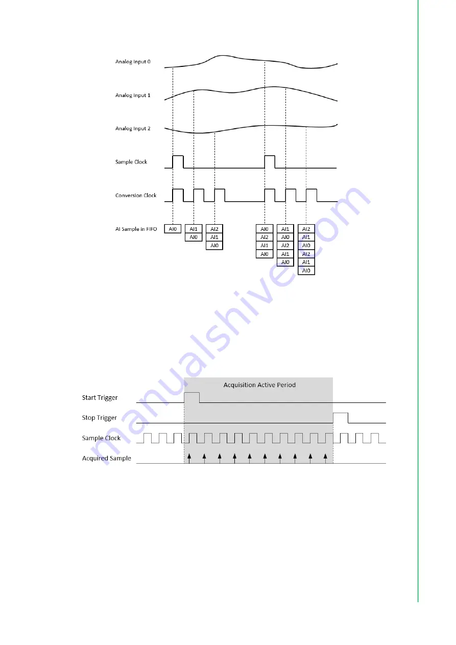
Figure 3.2 Buffered analog input acquisition.
The start and stop mechanism of the data acquisition are controlled by the start trig
-
ger and stop trigger respectively. When configuration is completed, the acquisition
engine of the iDAQ chassis is at standby state. After receiving a start trigger, acquisi
-
tion becomes active and each rising edge of the sample clock acquires one analog
input sample. The acquisition active period lasts until a stop trigger is received, which
ends the acquisition. This is shown in Figure 3.3.
Figure 3.3 Start and stop triggers of the analog input acquisition.
The start and stop of data acquisition can also be delayed in the number of samples
after receiving the corresponding trigger signal. As shown in Figure 3.4, the start of
acquisition is delayed by 3 samples after receiving a start trigger, and the stop of
acquisition is delayed by 2 samples after receiving a stop trigger.
Summary of Contents for iDAQ-817
Page 1: ...User Manual iDAQ 817 iDAQ 821 Analog Input and output Industrial DAQ Modules ...
Page 8: ...iDAQ 817_821 User Manual viii ...
Page 11: ...Chapter 1 1 Start Using iDAQ 817 821 ...
Page 15: ...Chapter 2 2 Installation Guide ...
Page 20: ...iDAQ 817_821 User Manual 10 ...
Page 21: ...Chapter 3 3 Function Details ...
Page 29: ...Appendix A A Specifications ...
Page 33: ...Appendix B B System Dimensions ...
Page 35: ...25 iDAQ 817_821 User Manual Appendix B System Dimensions ...


