


HPC-7480 User Manual
6
2.1
Overview
The following procedures instruct users on how to install a backplane/motherboard,
add-on cards and disk drives into the HPC-7480. Please also refer to Appendix A,
Exploded Diagram, for the detailed parts of HPC-7480.
2.2
Removing the Chassis Cover
2.2.1
Disconnecting the Chassis from the Power Source
1.
Turn off all peripheral devices and turn off the power supply to the HPC-7480.
2.
Disconnect the AC power cords from the system.
3.
Disconnect all cables and label the cables for easy identification.
After completing the above steps, you can remove the chassis cover and install com-
ponents and devices into the chassis as described in this chapter.
2.2.2
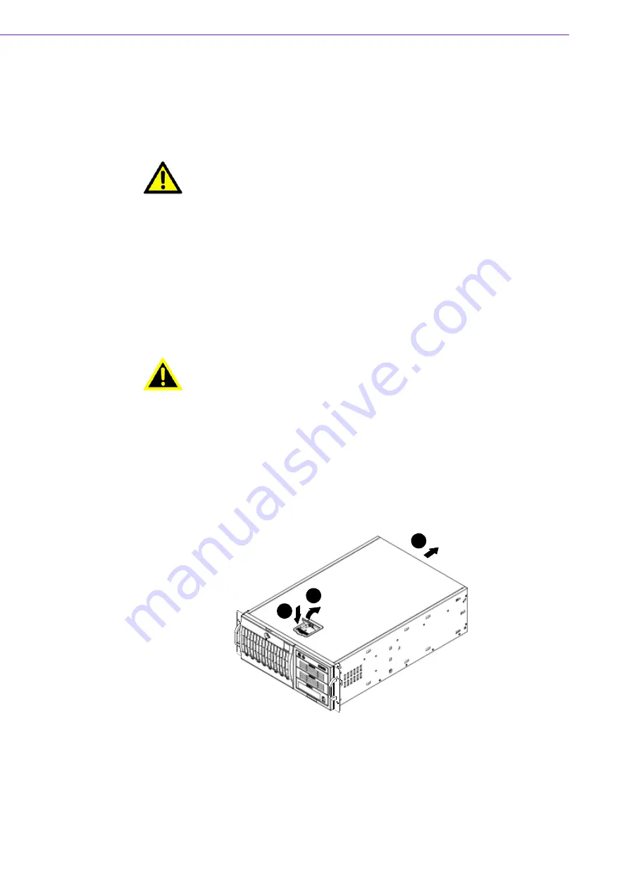
Removing the Chassis Cover
1.
Press the release tab to unlock the cover.
2.
The release tab will pop open as shown.
3.
Slide the cover back and off of the chassis.
Figure 2.1 Removing the Chassis Cover
Caution!
Use caution when installing or operating the components with the chas-
sis open. Be sure to turn off the power, unplug the power cord and
ground yourself by touching the metal chassis before you handle any
components inside the machine.
Warning!
Use a grounded wrist strap designed to prevent static discharge when
handling components.
1
1
1
2
1
3
Summary of Contents for HPC-7480
Page 6: ...HPC 7480 User Manual vi...
Page 9: ...Chapter 1 1 General Information...
Page 12: ...HPC 7480 User Manual 4...
Page 13: ...Chapter 2 2 System Setup...
Page 21: ...Chapter 3 3 Operation...
Page 25: ...Chapter 4 4 SATA SAS Backplane...
Page 39: ...Appendix A A Chassis Screws...
Page 41: ...33 HPC 7480 User Manual Appendix A Chassis Screws...


