Raymar RM16M VAC-R, User Manual
The Raymar RM16M VAC-R is a versatile and efficient vacuum cleaner, designed to simplify your cleaning tasks. Featuring a powerful motor and advanced features, this product guarantees exceptional performance. Get the most out of your vacuum with the free user manual available for download from our website.
Share
Download


Reviews:
No comments
Related manuals for RM16M VAC-R
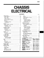
55624R(S)-MF
Brand: Mitsubishi Electric Pages: 180

A-F5000
Brand: HP Pages: 97

A-F5000
Brand: HP Pages: 145

NEO 200S
Brand: Overland Storage Pages: 3

FL1000 Series
Brand: ADC Pages: 4

1RK-CHASSIS ONErack
Brand: Tvone Pages: 8

cDAQ-9138
Brand: National Instruments Pages: 6
ION219-x
Brand: Lantronix Pages: 34

TEG-S3000I - TEG Gigabit Layer 2 Managed Chassis S3000i Switch
Brand: TRENDnet Pages: 11

PRO-LCD
Brand: nMedia Pages: 40

D Frame 2.0
Brand: In Win Pages: 15


