FWA-1320 User Manual
62
3.5.1.2
USB DOM
You need:
a PH2 screw driver
a standard USB DOM
To remove a USB DOM proceed in the reverse of the installation procedure in section
3.3.1.2:
1.
Remove the USB DOM mounting screw..
2.
Extract the USB DOM by pulling the DOM upwards evenly. Be sure not to bend
any USB DOM connector pins.
3.
Install a new SSD following the mounting instructions of the same section.
3.5.1.3
mSATA SSD
You need:
a PH1 screw driver
a standard mSATA SSD
To remove a mSATA SSD proceed in the reverse of the installation procedure in sec-
tion 3.3.1.3:
1.
Remove the mSATA mounting screw. Please be sure to hold the screw as the
spring mechanism in the mSATA connector will flip the mSATA module upwards
once the screw is lose.
2.
Extract the mSATA module
Install a new SSD following the mounting instructions of the same section.
3.5.2
CMOS Battery
You need:
A BR2032 battery
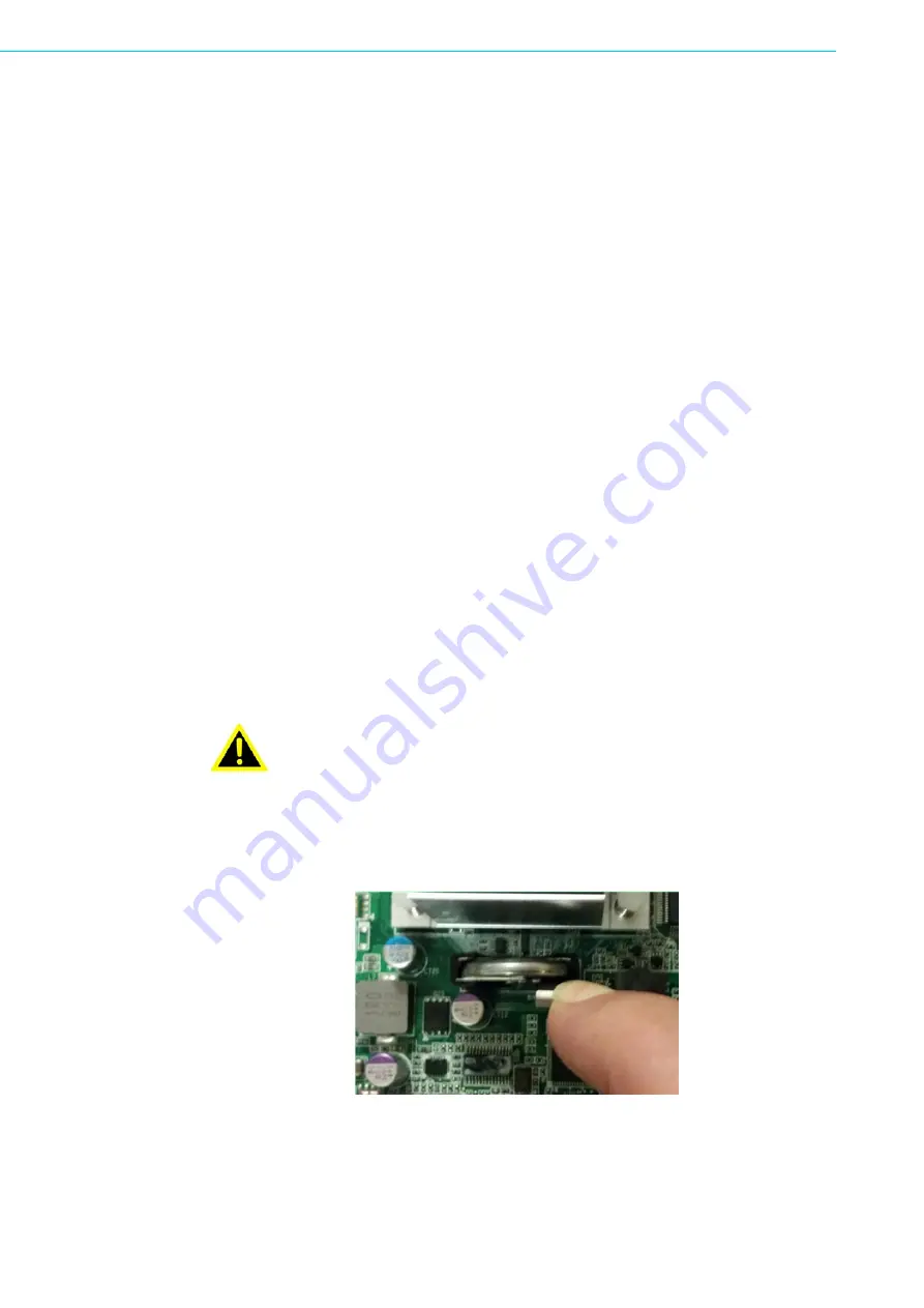
To replace the RTC’s battery located at B1, pull the spring clip securing the battery
forward with your finger tip. Please handle with care and do not bend the spring clip.
Then extract the battery vertically.
Figure 3.34 Unlocking the battery
Keeping the spring clip pulled towards you, insert the replacement battery.
Please make sure you insert the battery in correct polarity with the positive pole fac-
ing the front panel and the negative pole facing the CPU heatsink. Trying to insert the
Warning!
There is the danger of explosion if the battery is replaced incorrectly.
Replace the battery only with the same or equivalent type specified
above.
Dispose of used batteries according to the manufacturer's instructions.
Summary of Contents for FWA-1320
Page 1: ...User Manual FWA 1320 TABLETOP NETWORK APPLIANCE BASED ON INTEL ATOM C2000 SYSTEM ON CHIP ...
Page 6: ...FWA 1320 User Manual vi ...
Page 11: ...Chapter 1 1 Getting Started ...
Page 16: ...FWA 1320 User Manual 6 Figure 1 3 PuTTY Keyboard Settings Figure 1 4 PuTTY Colour Settings ...
Page 23: ...Chapter 2 2 Product Specification ...
Page 42: ...FWA 1320 User Manual 32 ...
Page 43: ...Chapter 3 3 Configuration and Service ...
Page 74: ...FWA 1320 User Manual 64 ...
Page 75: ...Appendix A A Connector Pinout and LED Information ...
Page 78: ...FWA 1320 User Manual 68 ...
Page 79: ...Appendix B B BIOS Post Codes ...
Page 84: ...FWA 1320 User Manual 74 ...
Page 85: ...Appendix C C Declaration of Conformity ...
Page 87: ...Appendix D D Warranty and RMA ...
Page 89: ...79 FWA 1320 User Manual Appendix D Warranty and RMA ...


