


EKI-1242NR Series User Manual
9
2.3
Installing the Fieldbus Gateway
2.3.1
DIN Rail Mounting
The DIN rail mount option is the quickest installation option. Additionally, it optimizes
the use of rail space.
The metal DIN rail kit is secured to the rear of the fieldbus gateway. The device can
be mounted onto a standard 35 mm (1.37”) x 7.5 mm (0.3”) height DIN rail. The
devices can be mounted vertically or horizontally. Refer to the following guidelines for
further information.
2.3.1.1
Installing the DIN-Rail Mounting Kit
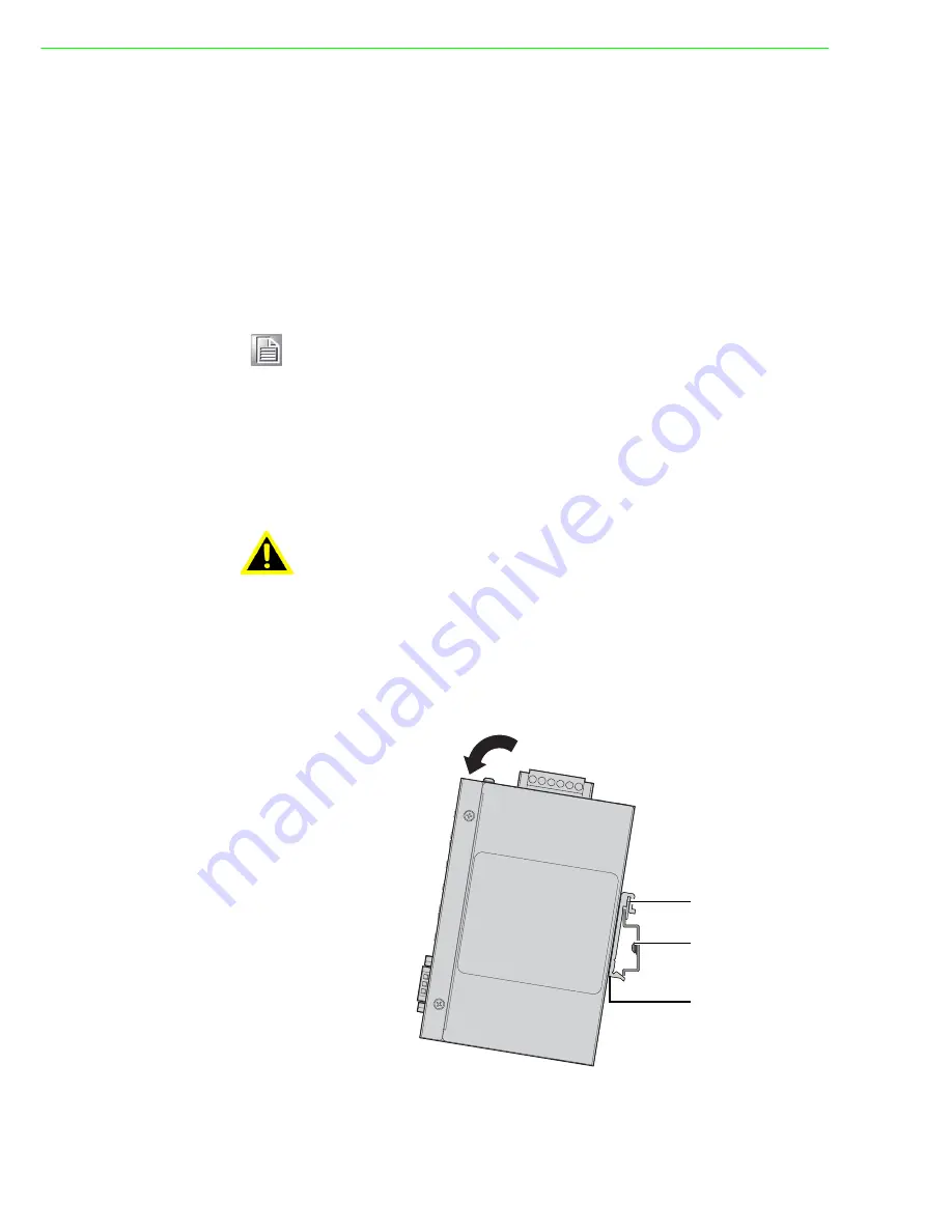
1.
Position the rear panel of the fieldbus gateway directly in front of the DIN rail,
making sure that the top of the DIN rail clip hooks over the top of the DIN rail, as
shown in the following illustration.
Make sure the DINrail is inserted behind the spring mechanism.
2.
Once the DIN rail is seated correctly in the DIN rail clip, press the front of the
fieldbus gateway to rotate the fieldbus gateway down and into the release tab
on the DIN rail clip.
If seated correctly, the bottom of the DIN rail should be fully inserted in the
release tab.
Figure 2.1 Installing the DIN-Rail Mounting Kit
Note!
A corrosion-free mounting rail is advisable.
When installing, make sure to allow for enough space to properly install
the cabling.
Warning!
Do not install the DIN rail under or in front of the spring mechanism on
the DIN rail clip to prevent damage to the DIN rail clip or the DIN rail.
DIN rail clip
DIN rail
DIN rail clip
release tab


