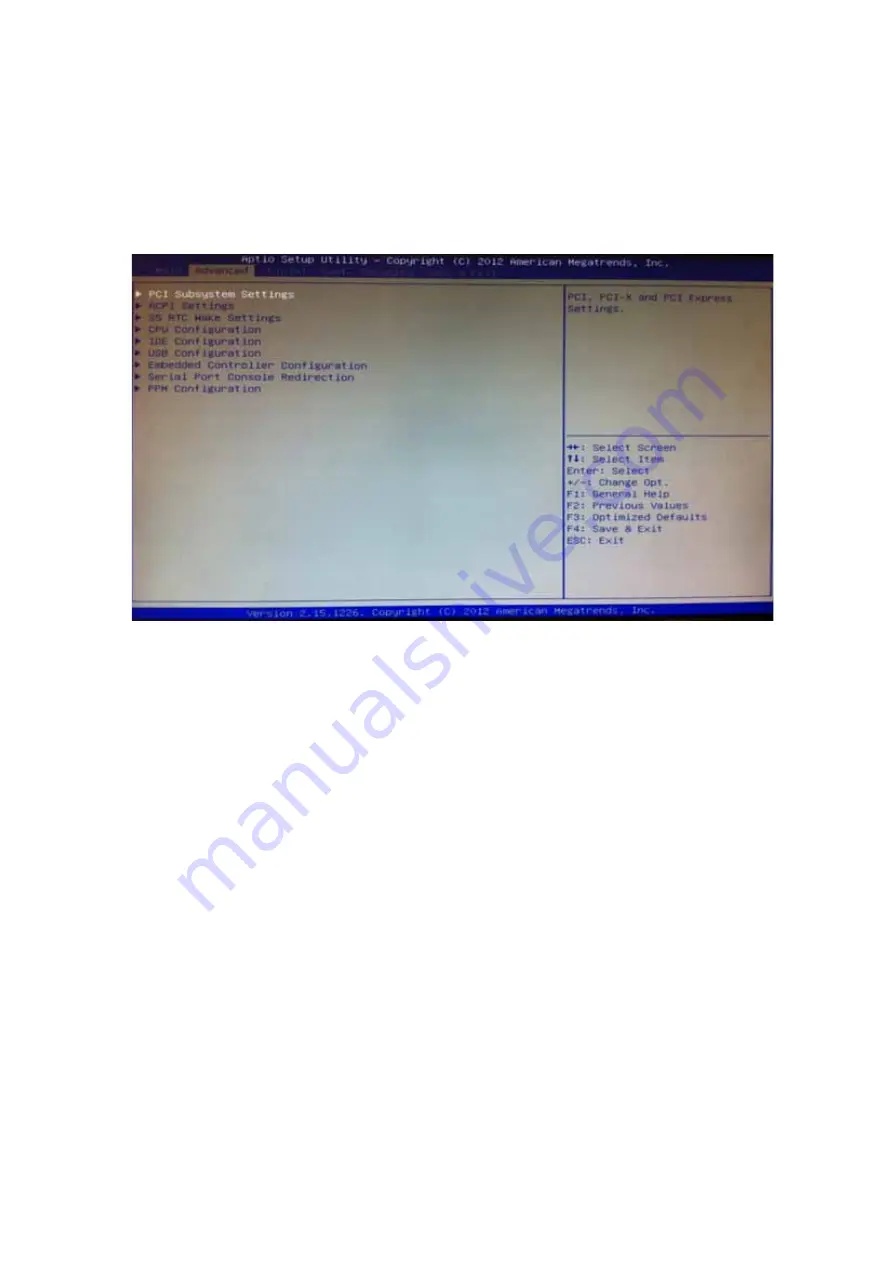
background image

20


3.2.2


Advanced


BIOS


Features


Setup


Select


the


Advanced


tab


from


the


DS

565


setup


screen


to


enter


the


Advanced


BIOS


Setup


screen.


You


can


select


any


of


the


items


in


the


left


frame


of


the


screen,


such


as


CPU


configuration,


to


go


to


the


sub


menu


for


that


item.


You


can


display


an


Advanced


BIOS


Setup


option


by


highlighting


it


using


the


<Arrow>


keys.


All


Advanced


BIOS


Setup


options


are


described


in


this


section.


The


Advanced


BIOS


Setup


screens


are


shown


below.


The


sub


menus


are


described


on


the


following


pages.


Figure.


18


Advanced


BIOS


Features


Setup


Screen


ACPI Settings: 

This


section


allows


you


to


control


hardware


monitoring


and


power


management


CPU Configuration:   


Hyper

threading:


Enabled


for


Windows


XP


and


Linux


(OS


optimized


for


Hyper

Threading


Technology)


and


Disabled


for


other


OS


(OS


not


optimized


for


Hyper

Threading


Technology).


When


disabled,


only


one


thread


per


enabled

core


is


enabled.


Active


Processor


Cores:


Number


of


cores


to


be


enabled


in


each


processor


package.


Limit


CPUID


Maximum:


Disabled


for


Windows


XP.


Execute Disable Bit: 

It


can


prevent


certain


classes


of


malicious


buffer


overflow


attacks


when


combined


with


a


supporting


OS


(Windows


Server


2003


Sp1,


Windows


XP


SP2,


SuSE


Linux


9.2


RedHat


Enterprise


3


Update


3.).


Intel


Virtualization


Technology:


When


enabled,


a


VMM


can


utilize


the


additional


hardware


capabilities


provided


by


Vander


pool


Technology.


Hardware


Prefetcher:


To


turn


on/off


the


Mid


Level


Cache


(L2)


streamer


prefetcher.


Adjacent


Cache


Line


Prefetch:


To


turn


on/off


prefetching


of


adjacent


cache


lines


Summary of Contents for DS-563SQ-S6A1E

Page 1: ...1 DS 563SQ S6A1E Computer...

Page 2: ...ich may result from its use Acknowledgements Award is a trademark of Award Software International Inc IBM PC AT PS 2 and VGA are trademarks of International Business Machines Corporation Intel and ATO...

Page 3: ...t when the problem occurs 2 Call your dealer and describe the problem Please have your manual product and any helpful information readily available 3 If your product is diagnosed as defective obtain a...

Page 4: ...ating system version application software etc A complete description of the problem The exact wording of any error messages Warnings Cautions and Notes Warning Warnings indicate conditions which if no...

Page 5: ...ception which can be determined by turning the equipment off and on the user is encouraged to try to correct the interference by one of the following measures Reorient or relocate the receiving antenn...

Page 6: ...lectrical shock 13 Never open the equipment For safety reasons the equipment should be opened only by qualified service personnel 14 If one of the following situations arises get the equipment checked...

Page 7: ...splay port for picture perfect content reproduction DS 565 also supports 1x Giga LAN 1x COM ports 4x USB2 0 giving a great selection for data communication in display applications The entire design ma...

Page 8: ...d 1Gbps Orange 100Mbps Green 10Mbps Off Interface 1 x RJ 45 jacks with LED Standard MDI copper IEEE802 3 Ethernet Interface for 1000BASE T 100BASE TX and 10BASE T applications 802 3 802 3u and 802 3ab...

Page 9: ...9 1 5 Mounting Kit 1 5 1 Dimension Figure 2 AC_TRAY_ANGLE_3 Figure 3 ANGLE_BASE...

Page 10: ...10 Figure 4 ANGLE_CB Figure 5 ANGLE_CT Warning Use suitable mounting apparatus to avoid risk of injury...

Page 11: ...on with brackets Figure 6 System with Brackets top view Figure 7 System with brackets bottom view Note This pair of wallmount bracket is designed for side of chassis and bottom side Reverse installati...

Page 12: ...19V DC in Model name Output rated Tma degree C FSP065 RAB 19VDC 3 42A 40 5 ADP_65JH ABCD 19VDC 3 42A 40 5 CAUTION Provided with each unit This product is intended to be supplied by an UL certified po...

Page 13: ...pecifications 1 7 1 Operating Temperature 5 C 50 C 23 F 122 F 1 7 2 Relative Humidity 95 40 C non condensing 1 7 3 Storage Temperature 40 60 4 F 140 F 1 7 4 Vibration Loading During Operation 5 500Hz...

Page 14: ...a power ON OFF button on the front side Push this button to turn the system ON and OFF It also supports a 5 second delay soft power off Figure 8 Power ON OFF Button 2 2 2 COM Connector DS 565 provide...

Page 15: ...Data 4 GND 2 2 4 Ethernet Connector LAN DS 565 provides one RJ 45 LAN interface connector fully compliant with IEEE802 3u 10 100 1000 Base T CSMA CD standards The Ethernet port provides a standard RJ...

Page 16: ...n receptacle connector HDMI Type A Interface is provided The HDMI link supports resolutions up to 1920x1080 HDMI VGA Figure 13 HDMI Connector Table 4 DisplayPort Pin out Pin Signal Name 1 TMDS Data 2...

Page 17: ...ule secure HDD to HDD bracket with 2 screws 2 Install a HDD module into DS 565 then secure it with a screw Figure 14 HDD Installation Figure 15 System Installation SATA connector HDD bracket Screw 1 S...

Page 18: ...ry Installation 1 Be easy to install remove memory on bottom cover 2 Remove memory cover and replace memory inside 3 Install the memory cover then secure with screw Figure 16 Memory Installation Memor...

Page 19: ...Main setup screen You can always return to the Main setup screen by selecting the Main tab The Main BIOS setup screen has two main frames The left frame displays all the options that can be configured...

Page 20: ...ation Hyper threading Enabled for Windows XP and Linux OS optimized for Hyper Threading Technology and Disabled for other OS OS not optimized for Hyper Threading Technology When disabled only one thre...

Page 21: ...TA Device SATA Mode Selection Determines how SATA controller s operate The choice IDE AHCI RAID Figure 20 SATA Setting page PCH FW Configuration Configuration Management Engine Technology Parameters A...

Page 22: ...boot USB Configure Enable Disable USB Configure function PET Progress User can Enable Disable PET Events progress to receive PET events or not WatchDog Enable Disable WatchDog Timer Figure 21 AMT Conf...

Page 23: ...uration Set Parameters of Serial port 0 COM Figure 23 Serial Port 0 Configuration setting CPU PPM Configuration CPU PPM Configuration Parameters EIST Enable Disable Intel SpeedStep Turbo Mode Turbo Mo...

Page 24: ...item in the left frame of the screen such as PCH IO Configuration and System Agent Configuration 3 2 4 Security BIOS Feature Setup Select the BOOT tab from the setup screen to enter the Security BIOS...

Page 25: ...et the system after saving the changes Discard Changes and Reset Reset system setup without saving any changes Save Changes Save Changes done so far to any of the setup options Discard Changes Discard...

Page 26: ...26...

Reviews: