


19
Chapter
3
BIOS
Settings
This chapter introduces how to set BIOS configuration data.
3.1
BIOS
Introduction
AMIBIOS
has
been
integrated
into
many
motherboards
for
over
two
decades.
With
the
AMIBIOS
Setup
program,
you
can
modify
BIOS
settings
and
control
various
system
features.
This
chapter
describes
the
basic
navigation
of
the
DS
‐
565
series
BIOS
setup
screens.
AMIBIOS’s
ROM
has
a
built
‐
in
setup
program
that
allows
users
to
modify
the
basic
system
configuration.
This
information
is
stored
in
battery
‐
backed
CMOS
so
it
retains
the
setup
information
when
the
power
is
turned
off.
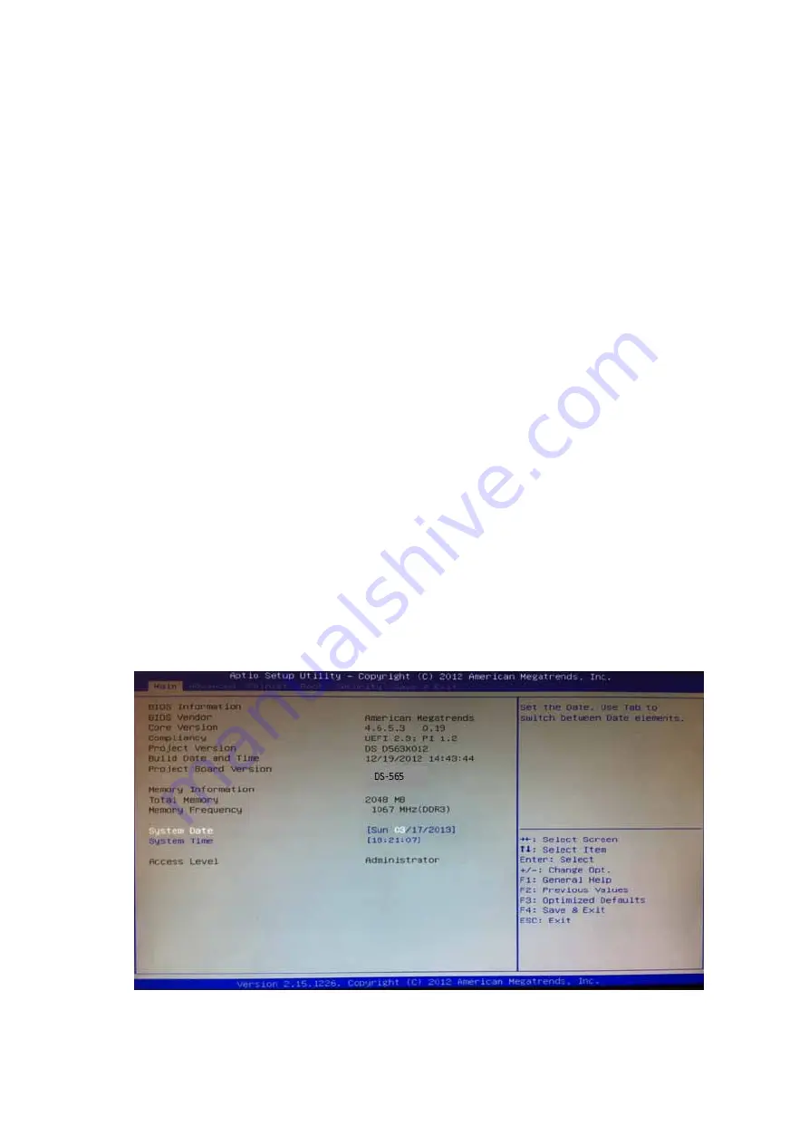
3.2
Main
Setup
When
you
first
enter
the
BIOS
Setup
Utility,
you
will
enter
the
Main
setup
screen.
You
can
always
return
to
the
Main
setup
screen
by
selecting
the
Main
tab.
The
Main
BIOS
setup
screen
has
two
main
frames.
The
left
frame
displays
all
the
options
that
can
be
configured.
Options
in
blue
can
be
configured,
and
grayed
‐
out
options
cannot
be
configured
instead.
The
right
frame
displays
the
key
legend.
The
key
legend
in
the
top
is
an
area
reserved
for
a
text
message.
When
an
option
is
selected
in
the
left
frame,
it
is
highlighted
in
white.
Often
a
text
message
will
accompany
it.
3.2.1
System
Time/
System
Date
Use
this
option
to
change
the
system
time
and
date.
Highlight
System
Time
or
System
Date
using
the
<Arrow>
keys.
Enter
new
values
through
the
keyboard.
Press
the
<Tab>
key
or
the
<Arrow>
keys
to
move
between
fields.
The
date
must
be
entered
in
MM/DD/YY
format.
The
time
must
be
entered
in
HH:MM:SS
format.
Figure.
17
Main
Setup
Screen