


17
2.3
Hardware
Installation
2.3.1
HDD
Installation
(1)
To
assembly
a
HDD
module,
secure
HDD
to
HDD
bracket
with
2
screws.
(2)
Install
a
HDD
module
into
DS
‐
565,
then
secure
it
with
a
screw.
Figure.
14
HDD
Installation
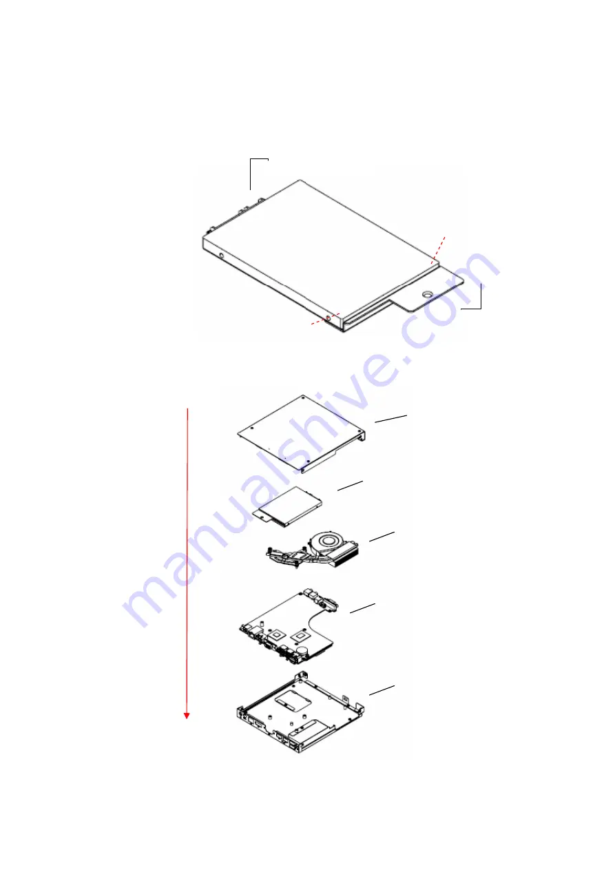
Figure.
15
System
Installation
SATA
connector
HDD
bracket
Screw
1
Screw
2
HDD
Module
Top
cover
FAN
Module
M/B
Bottom
cover
Installed
direction