


6
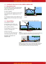
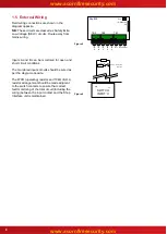
1.5 External Wiring
Figure 5
Field wiring connections are shown in the
diagram opposite.
NB:
These circuits are classed as Safety Extra
Low Voltage (SELV) circuits. Route away from
mains wiring.
Inputs A and B can be monitored for open and
short circuit conditions.
The monitored inputs circuits should be wired as
per the diagram opposite.
The 470Ω (operating) resistor and 10kΩ (E.O.L)
resistor arrangement should be made adjacent
to the switch contacts to ensure that correct
fault monitoring of the total circuit (including the
wiring) between the input contact and the Shop
Interface unit is maintained.
Figure 6
TB3
TB2
TB1
IN
A
RL1 RL2 Power
TO DISPLAY
Mxp-029
PL1
PL2
IN
B
IN
C
IN
D
IN
E
+
–
SWITCH
INPUT 'n'
470R ¼W
10K ¼W
Volt free
contact


