


4
1 Installation
1.1 Installing the Mxp-029 in the Mx-4100/L
1.1.1 Mounting the Card
Base Card
M3 Fixing Points (x4)
PL
2
PL
5
Mxp-029
TB3
TB1
TB5
PL1
PL1
Ribbon Cable 1
Ribbon Cable 2
DC 24V
DC 24V
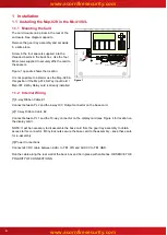
Figure 1
The card mounts on 4 pillars in the rear of the
enclosure. See diagram opposite.
Remove the gear tray assembly and set aside
in a safe place.
Screw in the four spacers supplied into the
threaded inserts in the back box. Use the four
M3 screws supplied to securely affix the card to
the spacers.
Figure 1 opposite shows the location.
It is not possible to install or use the Mxp-029 in
this position if the Mxp-014 8-Way Input Card /
Mxp-007 2-Way Relay card is already installed.
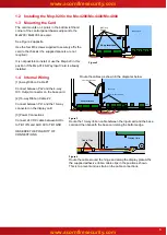
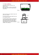
1.1.2 Internal Wiring
[1] 4-way Ribbon Cable #1
Connect between PL2 and the 4-way O/C Output connector on the base card.
[2] 10-way Ribbon Cable #2
Connect between PL1 and the 10-way connector on the display card (see Figure 4 for location on
the display card).
NOTE: It will be necessary to disassemble the base card from the gear tray assembly to obtain
access to this connector. M3 nylock nuts secure the base card to the assembly
– keep these safe
for re-assembly.
[3] Power Connections
Connect 24V DC cable between AUX+ to TB1 VIN and AUX 0V to TB1 GND.
Run the cable along the rear wall of the back box and tie in place with cable ties. OBSERVE THE
POLARITY OF CONNECTIONS.


