


5
1.2 Installing the Mxp-029 in the Mx-4200/Mx-4400/Mx-4800
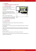
1.3 Mounting the Card
M3 Fixing
Screws
Base Card
TB3
Shop Interface
Figure 2
The card mounts on 4 pillars in the bottom left hand
corner of the control panel chassis adjacent to the
Mx4200 / Mx4400 base card.
See Figure 2 opposite.
Use the four M3 screws supplied to securely affix the
card to the chassis (the supplied spacers are not
required).
It is not possible to install or use the Mxp-029 in this
position if the Mxp-014 8-Way Input Card is already
installed.
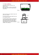
1.4 Internal Wiring
Route the cables as shown in the diagrams below.
DC SUPPLY
Base Card
TB3
10-way Ribbon Cable 2
Shop Interface
4-way Ribbon Cable 1
Figure 3
Route the 10-way ribbon cable between the input card and the base
card and then beneath the base card along the bottom edge.
Display Card
Cable Clips
Figure 4
Route the cable around the hinge and along the display plate. Affix
the supplied adhesive ribbon cable clips in the positions shown.
This is to prevent undue strain on the cable connections.
[1] 4-way Ribbon Cable #1
Connect between PL2 and the 4-way
O/C Output connector on the base card.
[2] 10-way Ribbon Cable #2
Connect between PL1 and the 10-way
connector on the display card.
[3] Power Connections
Connect 24V DC cable between AUX+
to TB1 VIN and AUX 0V to TB1 GND.
OBSERVE THE POLARITY OF
CONNECTIONS


