background image


Shop Interface Unit 

The operation and functions described in this manual are available from Software Version 4000-016-00 onwards. 


Features 

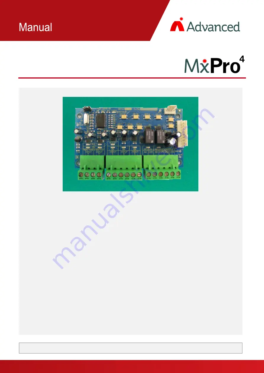
The  Shop  Interface  Unit  allows  MxPro  4  control  panels  to  send  and  receive  alarm  signals  from  other 
equipment. 
 
Input signals  can  be  received  from  clean-contact  inputs,  with two  of  the  inputs  also  supporting      open  circuit 
and short circuit fault monitoring on the external wiring.  
 
A  special  input  is  also  able  to  differentiate  between  an  input  that  is  pulsing  (ALERT)  or  is  on  continuously 
(EVAC),  allowing  easy  interfacing  to  older  equipment  that  cannot  provide  independent  Alert  and  Evacuate 
signals.  
 
Two fully programmable outputs are also provided to allow signals to be transmitted out to other equipment. 


www.acornfiresecurity.com

www.acornfiresecurity.com

Summary of Contents for MxPro 4

Page 1: ...t inputs with two of the inputs also supporting open circuit and short circuit fault monitoring on the external wiring A special input is also able to differentiate between an input that is pulsing AL...

Page 2: ...chassis Compatibility The Shop Interface unit mounts in the MxPro 4 panels as follows Mx 4200 Mx 4400 Mx 4800 control panels directly onto the chassis Mx 4100 L control panel on the rear face of the...

Page 3: ...Mounting the Card 4 1 1 2 Internal Wiring 4 1 2 INSTALLING THE MXP 029 IN THE MX 4200 MX 4400 MX 4800 5 1 3 MOUNTING THE CARD 5 1 4 INTERNAL WIRING 5 1 5 EXTERNAL WIRING 6 2 CONFIGURATION 7 2 1 ALERT...

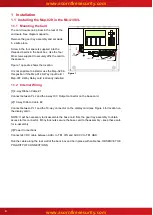
Page 4: ...tion if the Mxp 014 8 Way Input Card Mxp 007 2 Way Relay card is already installed 1 1 2 Internal Wiring 1 4 way Ribbon Cable 1 Connect between PL2 and the 4 way O C Output connector on the base card...

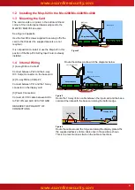
Page 5: ...PLY Base Card TB3 10 way Ribbon Cable 2 Shop Interface 4 way Ribbon Cable 1 Figure 3 Route the 10 way ribbon cable between the input card and the base card and then beneath the base card along the bot...

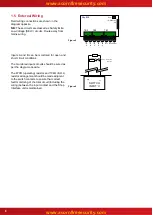
Page 6: ...s should be wired as per the diagram opposite The 470 operating resistor and 10k E O L resistor arrangement should be made adjacent to the switch contacts to ensure that correct fault monitoring of th...

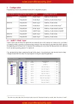
Page 7: ...ction 2 1 ALERT EVAC Input Input C can be used to detect if a signal from an external source is off pulsing or on continuous e g to detect an ALERT or EVAC signal from an external clean contact The sh...

Page 8: ...gram below shows these relays allocated to output Groups 190 191 respectively these group numbers are arbitrary any output group can be used For ease of recognition the text for each input has also be...

Page 9: ...USER NOTES www acornfiresecurity com www acornfiresecurity com...

Page 10: ...www acornfiresecurity com www acornfiresecurity com...

Reviews: