background image

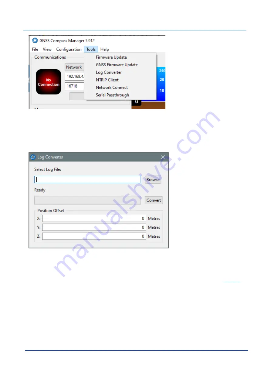
Figure 47: GNSS Compass Manager Tools Menu

8.2.8.1 Log Converter

This tool allows the user to convert GNSS Compass log files into various standard formats that are readable by
many programs. The offset is used to project the exported position to a point other than the centre of the GNSS
Compass unit. For most users these values should be left at zero.

Figure 48: GNSS Compass Manager Log Converter Dialogue

8.2.8.2 NTRIP Client

The NTRIP client can be used to connect to a network DGPS or RTK service to stream correction data to GNSS
Compass for DGPS or RTK. The NTRIP client requires an internet connection to function. Contact

Support

for

guidance on getting set up with network DGPS or RTK.

v2.0

Page 62

04 Nov 2021

GNSS Compass Reference Manual • Configuring and Monitoring GNSS Compass

Summary of Contents for GNSS Compass

Page 1: ...GNSS Compass Reference Manual v2 0 04 Nov 2021 ...

Page 2: ... Accessories 11 5 Specifications 12 5 1 Navigation Specifications 12 5 1 1 GNSS Specifications 12 5 2 Hardware Specifications 13 5 2 1 Ethernet Variant 13 5 2 2 Serial Variant 13 5 2 3 Mechanical Drawings 14 5 2 4 Axes 15 5 2 5 Serial Number 15 5 3 Communication Specifications 17 5 3 1 Ethernet Variant 17 5 3 2 Serial Variant 17 5 4 Electrical Specifications 17 5 5 Certification 18 6 Installing GN...

Page 3: ...Initialisation 30 7 1 4 Time Initialisation 30 7 2 Hot Start 30 7 3 Time 31 7 4 Heading Sources 31 7 4 1 Dual Antenna Heading 31 7 4 2 External Heading 31 7 5 NMEA 2000 31 7 6 NMEA 0183 32 7 7 Sensor Ranges 34 7 8 Vehicle Profiles 34 7 9 RTK 34 7 9 1 Network RTK Corrections NTRIP 34 7 9 2 Radio Modem RTK Corrections 35 7 9 3 Supported RTCM Messages 35 7 10 Heave 36 7 11 Environmental Exposure 36 7...

Page 4: ...Receiver Information 46 8 1 3 Configuration Menu 47 8 1 3 1 Sensor Ranges 47 8 1 3 2 Filter Options 47 8 1 3 3 Data Ports 47 8 1 3 4 Alignment 48 8 1 3 5 Reset 48 8 1 3 6 Manual Initialisation 49 8 1 3 7 Ethernet Settings 49 8 1 3 8 NTRIP Client 50 8 1 4 Tools Menu 51 8 1 4 1 Firmware Update 51 8 2 Using GNSS Compass Manager 52 8 2 1 Software Changelog 53 8 2 2 System Requirements 53 8 2 3 Install...

Page 5: ... Functions 66 9 1 2 1 NMEA Input 67 9 1 2 2 ANPP Input 67 9 1 2 3 NMEA Output 68 9 1 2 4 ANPP Output 68 9 1 2 5 TSS1 Output 68 9 1 2 6 Simrad 1000 Output 68 9 1 2 7 Simrad 3000 Output 68 9 1 2 8 GNSS Receiver Passthrough 69 9 2 Serial Interface 69 9 2 1 Baud Rate 69 9 2 2 Format 69 9 3 1PPS Signal 69 9 4 CAN Interface 69 10 Advanced Navigation Packet Protocol 70 10 1 About Packets 73 10 1 1 Packet...

Page 6: ...4 1 3 GNSS Fix Status 86 10 4 1 4 Unix Time Seconds 87 10 4 1 5 Microseconds 87 10 4 2 Unix Time Packet 87 10 4 3 Formatted Time Packet 87 10 4 4 Status Packet 88 10 4 5 Position Standard Deviation Packet 88 10 4 6 Velocity Standard Deviation Packet 88 10 4 7 Euler Orientation Standard Deviation Packet 89 10 4 8 Quaternion Orientation Standard Deviation Packet 89 10 4 9 Raw Sensors Packet 90 10 4 ...

Page 7: ...1 Satellite Systems 105 10 4 36 2 Satellite Frequencies 105 10 4 36 3 Tracking Status 106 10 4 37 GNSS Receiver Information Packet 106 10 4 37 1 GNSS Manufacturer IDs and Receiver Models 106 10 4 37 2 RTK Software License Accuracy 107 10 4 38 Automotive Packet 107 10 4 39 External Magnetometers Packet 108 10 4 39 1 External Magnetometers Flags 108 10 5 Configuration Packets 108 10 5 1 Packets Peri...

Page 8: ... 10 5 9 3 Output Rates Index 120 10 5 10 User Data Packet 120 11 Reference Information 121 11 1 Technology Overview 121 11 1 1 GNSS 121 11 1 2 AHRS 121 11 1 3 INS 121 11 1 4 GNSS INS 121 11 2 The Sensor Co ordinate Frame 122 11 3 The Body Co ordinate Frame 123 11 4 Roll Pitch and Heading 123 11 4 1 Second Right Hand Rule 124 11 4 2 Rotation Order 124 11 5 Geodetic Co ordinate System 124 11 6 NED C...

Page 9: ...CED NAVIGATION DISCLAIMS ANY EXPRESS OR IMPLIED WARRANTY WITH RESPECT TO THE USE AND OR SALE OF ADVANCED NAVIGATION PRODUCTS INCLUDING WITHOUT LIMITATION IMPLIED WARRANTIES OF MERCHANTABILITY FITNESS FOR A PARTICULAR PURPOSE AND THEIR EQUIVALENTS UNDER THE LAWS OF ANY JURISDICTION OR INFRINGEMENT OF ANY PATENT COPYRIGHT OR OTHER INTELLECTUAL PROPERTY RIGHT UNLESS EXPRESSLY APPROVED IN WRITING BY T...

Page 10: ...ed POE injector from AC to DC 1 1 13 Jan 2021 Updated 2 1 Firmware Changelog Updated 4 Part Numbers and Ordering Revised wording on 5 5 Certification Updated NMEA 0183 Added precise time protocol PTP 1 0 23 Jan 2018 Initial Release Table 1 Revision History v2 0 Page 1 04 Nov 2021 GNSS Compass Reference Manual Revision History ...

Page 11: ...roperly and operated with an awareness of its limitations Please read through this manual carefully to ensure success within your application Figure 1 GNSS Compass Note For information about Global Navigation Satellite Systems GNSS and related concepts explained in simple terms see 11 Reference Information Use the links below for detailed information about GNSS Compass l 4 Part Numbers and Orderin...

Page 12: ...gnetometer failure Bug fix for Raw Satellite Data packet always on always off Default vehicle profile changed to small boat Bug fix for cold start reset not working Heave fix 0 96 5 December 2017 Initial release firmware Table 2 Firmware Changelog Note To upgrade the firmware to the latest version see 7 12 Upgrading the GNSS Compass Firmware 2 2 Hardware Changelog Version Date Changes 2 0 23 Septe...

Page 13: ...4 3 Accessories 1 Install the GNSS Compass in an area where it has a full clear view of the sky and away from strong radio transmission sources as shown in Figure 2 GNSS Compass ideal mounting location Figure 2 GNSS Compass ideal mounting location 2 Ensure that the GNSS Compass is aligned with the vessel such that the indicator on top is aligned pointing forwards on the vessel The sight can be use...

Page 14: ...he cable into the GNSS Compass and rotate the nut clockwise to lock it in place See GNSS Compass connector locking Figure 4 GNSS Compass connector locking v2 0 Page 5 04 Nov 2021 GNSS Compass Reference Manual Getting Started with GNSS Compass ...

Page 15: ...ee 7 6 NMEA 0183 for further details on message configuration 3 3 Power over Ethernet Connection 1 Plug the Ethernet cable from the GNSS Compass into the Data Power port on the PoE injector Plug an Ethernet cable into the Data port and connect the other end to a DHCP router 2 Install zeroconf Apple Bonjour from one of the links below https www advancednavigation com au Bonjour msi 32 bit installer...

Page 16: ...ct a GNSS Compass unit They are available in both an Ethernet POE and Serial version 3 4 Evaluation Kit Contents The GNSS Compass Evaluation Kit Contents are detailed below for both the Ethernet and Serial variants v2 0 Page 7 04 Nov 2021 GNSS Compass Reference Manual Getting Started with GNSS Compass ...

Page 17: ...2 RS422 selectable 1 metre cable SUPPLY 24V 1 1 24 V DC power supply 100 240 V AC Mains to 24 V DC Power Supply DC jack Includes 2 pin plug types A C G I GC POE CABLE 20M 1 20m Ethernet cable for GNSS Compass 20m CAT5e Ethernet cable with RJ45 Compatible with Ethernet units only GC2 POE IP67 environmentally sealed connector See Ethernet Connection for full details GC SER BREAK 20M 1 20m serial bre...

Page 18: ...Part Number Quantity Description Notes Ethernet Serial DC Table 4 Evaluation Kit Contents v2 0 Page 9 04 Nov 2021 GNSS Compass Reference Manual Getting Started with GNSS Compass ...

Page 19: ...rt Num ber Description Notes GC2 POE GNSS Compass Ethernet Vari ant GNSS Compass Ethernet variant Power over Ethernet interface Supports GPS GLONASS Galileo BeiDou constellation L1 L2 10mm RTK Supports DGPS and SBAS Does not support L band No cables included GC2 SER GNSS Compass Serial Variant GNSS Compass Serial variant RS422 RS232 and CAN interfaces Supports GPS GLONASS Galileo BeiDou constellat...

Page 20: ...ated cable Compatible with serial units only GC2 SER IP67 environmentally sealed connector See Serial Connection for full details POE INJECTOR DC DC POE Injector 24V DC PoE Injector 25W 802 3at Type 2 PoE Requires 12 24V DC power supply SUPPLY 24V CAR12VPWR or similar SUPPLY 24V 24 V DC Power Supply 100 240 V AC Mains to 24 V DC Power Supply DC jack Includes 2 pin plug types A C G I CAR12VPWR Car ...

Page 21: ...sition Accuracy with RTK 0 01 m Vertical Position Accuracy with RTK 0 015 m Velocity Accuracy 0 05 m s Roll Pitch Accuracy 0 4 Heading Accuracy with Dual GNSS 0 2 Heave Accuracy whichever is greater 5 or 0 05 m Rotation Range Unlimited Hot Start Time orientation 1 s Internal Filter Rate 200 Hz Output Data Rate 200 Hz Table 8 GNSS Compass Navigation Specifications 5 1 1 GNSS Specifications Specific...

Page 22: ...mental Protection IP67 Shock Limit 75 g 11 ms Dimensions length x width x height 672 mm x 190 mm x 73 9 mm Weight 1450 grams Table 10 Hardware Specifications for GNSS Compass Ethernet 5 2 2 Serial Variant Specification Value Power Input 9 to 36 V Input Protection 40 to 60 V Power Consumption 1 4 W Operating Temperature 40 C to 85 C Environmental Protection IP67 Shock Limit 75 g 11 ms Dimensions le...

Page 23: ...5 2 3 Mechanical Drawings Figure 5 Mechanical Drawings of GNSS Compass v2 0 Page 14 04 Nov 2021 GNSS Compass Reference Manual Specifications ...

Page 24: ... web UI 8 1 2 View Menu l Through the Device Information page in the 8 2 Using GNSS Compass Manager application l Via the 2D data matrix bar code on the underside of the enclosure near the IO connector Applications are available for most smart phones that can scan the 2D data matrix bar code to display the serial number The label also contains the hardware version and build date v2 0 Page 15 04 No...

Page 25: ...Figure 7 GNSS Compass External Serial Number Sticker v2 0 Page 16 04 Nov 2021 GNSS Compass Reference Manual Specifications ...

Page 26: ...faces RS422 or RS232 CAN Speed 2400 to 1 M baud Protocols NMEA 0183 NMEA 2000 Advanced Navigation Packet Protocol TSS1 Simrad Timing 1PPS Output Timing Accuracy 20 ns Additional Interfaces Auxiliary RS422 RS232 1PPS Output Alarm Output Table 13 Serial Communication Specifications 5 4 Electrical Specifications Parameter Minimum Typical Maximum RS232 Tx Voltage Low 5 4 V 5 V Tx Voltage High 5 V 5 4 ...

Page 27: ...g Device THD GNSS method based on the Directive 2014 90 EU The Serial model GC2 SER is pending certification to the following standards IMO Standards ISO IEC Standards IMO Res MSC 116 73 ISO 22090 3 2014 IMO Res MSC 191 79 IEC 60945 2002 incl IEC 60945 Corr 1 2008 IMO Res A 694 17 IEC 61162 1 ed4 0 2010 11 IEC 61162 2 ed1 0 1998 09 IEC 62288 Ed 2 0 2014 07 Table 15 Standards for GC2 SER The Ethern...

Page 28: ......

Page 29: ...ce Table 17 Additional Information Note For ordering an evaluation kit a standalone kit or accessories for GNSS Compass see 4 Part Numbers and Ordering 6 1 Installation Checklist The GNSS Compass is designed to be plug and play such that it does not normally require any customer configuration Typical installations utilising NMEA 0183 or NMEA 2000 will work out of the box 6 1 1 Connection Options T...

Page 30: ...connection to an Ethernet network the Advanced Navigation Ethernet Connection is required part number GC POE CABLE 20M One end of the cable should be connected to the GNSS Compass and the other to either a PoE injector part number POE INJECTOR DC or 802 3af or 802 3at compliant PoE switch The PoE injector or switch is then connected to a router 6 1 1 4 ANPP For connection to an ANPP receiving devi...

Page 31: ...nk https www advancednavigation com Bonjour64 msi 4 Open a web browser and type in the address http gnss compass local to access the web interface 5 Using the Configuration menu options can be changed as required Changes to configuration are saved between power cycles and only need to be applied once The default username is admin and default password is password 6 2 Mounting GNSS Compass 6 2 1 Mou...

Page 32: ...ng Options The GNSS Compass can either be pole mounted or surface mounted See 5 2 3 Mechanical Drawings for details 6 2 2 1 Pole mounting If pole mounting the unit connection is via a single 1 14 UNS 2A thread The provided 1 nylon and 1 locking nut should be used to mount to a suitable mounting pole as illustrated in Figure 10 Pole mounting assembly v2 0 Page 23 04 Nov 2021 GNSS Compass Reference ...

Page 33: ...ded shoulder washers to provide a small gap between the GNSS Compass and the mounting surface This will help protect against warping or cracking of the unit on slightly uneven surfaces Note the shoulder washers will require a nominal 10mm hole in the mounting surface as shown in Figure 11 Surface mounting shoulder washer v2 0 Page 24 04 Nov 2021 GNSS Compass Reference Manual Installing GNSS Compas...

Page 34: ...is level with the vehicle and the indicator on the lid is directly forward of the sight see Figure 12 GNSS Compass alignment The sight can be used to visually align the indicator for best results See Figure 14 Alignment on a car for example mounting on a boat and Figure 14 Alignment on a car for example mounting on a car v2 0 Page 25 04 Nov 2021 GNSS Compass Reference Manual Installing GNSS Compas...

Page 35: ...t such that the X axis points forward towards the front of the vehicle and the Z axis points straight down towards the ground as shown below Figure 13 Alignment on a boat v2 0 Page 26 04 Nov 2021 GNSS Compass Reference Manual Installing GNSS Compass ...

Page 36: ...gnss compass local to discover the device and access the web interface If you cannot establish a connection using a DHCP capable network you can connect to and configure the GNSS Compass using the Primary port RS232 serial interface and the GNSS Compass Manager application Note A factory reset will re enable the DHCP Client and lose any static IP address settings 6 5 Vibration GNSS Compass is able...

Page 37: ...s to a plate which is then mounted to the platform through vibration isolation mounts Be mindful that a plate with very soft mounts may also cause problems with shifts in orientation over time v2 0 Page 28 04 Nov 2021 GNSS Compass Reference Manual Installing GNSS Compass ...

Page 38: ...ew in the web UI or 8 2 6 View Menu in the GNSS Compass Manager Figure 15 Initialisation Levels After all four levels of initialisation the GNSS Compass INS filter takes several minutes to achieve its full accuracy It is recommended to wait two minutes after initialisation for applications requiring high accuracy 7 1 1 Orientation Initialisation Orientation initialisation occurs automatically upon...

Page 39: ...h antennas are connected with an unobstructed view of the sky The system can be stationary or moving during this initialisation If velocity heading is enabled and the vehicle is moving this will be very fast If the system is hot starting then it will use the heading from the heading from when it was last switched off as the starting heading until another source becomes available Until the heading ...

Page 40: ... PTP broadcasts are sent whenever an Ethernet connection is established and cannot be disabled l For Ethernet variants part number GC2 POE A built in Network Time Protocol NTP server 7 4 Heading Sources There are several different heading sources available for GNSS Compass The heading sources can be configured using the Filter Options page in the Web UI see 8 1 Using the Web User Interface or in t...

Page 41: ...apid Update Rapid update of latitude and longitude 100 10 129026 COG SOG Rapid Update Rapid update of Course Over Ground COG and Speed Over Ground SOG 250 4 129029 GNSS Position Data Position and GNSS fix status 1000 1 129540 GNSS Satellites in View 1000 1 130578 Vessel Speed Components Longitudinal and transverse speed 250 4 Table 18 NMEA 2000 transmitted messages 7 6 NMEA 0183 The GNSS Compass s...

Page 42: ...tion GPGSV Disabled Enabled 1 Hz GNSS satellites in view GPHBT Disabled Enabled 0 167 Hz 60 seconds Heartbeat supervision sentence GPHDG Disabled Enabled 1 Hz Magnetic deviation and variation GPHDM Disabled Enabled 1 Hz Magnetic Heading GPHDT Enabled 8 Hz Enabled 8 Hz True heading GPHEV Disabled Enabled 1 Hz Heave GPRMC Enabled 8 Hz Enabled 8 Hz Time date latitude longitude and 2D velocity GPROT D...

Page 43: ... select it for use in the Filter Options page in the Web UI or GNSS Compass Manager For a list of the different vehicle profiles see 10 5 5 1 Vehicle Types If the wrong vehicle profile is selected it can cause a significant decrease in performance 7 9 RTK The GNSS Compass internal GNSS receiver supports RTK GNSS which uses correction data RTCM messages from a nearby base station to provide accurac...

Page 44: ...oth a base station and a radio modem receiver The base station is set up at a fixed location and transmits corrections to the radio modem receiver that is connected to the mobile GNSS Compass unit the rover The radio modem receiver and GNSS Compass unit must remain within radio range of the base station to receive these corrections The base station should be located no more than 50 km from the GNS...

Page 45: ...ruction of the internal electronics and the sealing is not designed for prolonged or repetitive immersion Do not direct streams of water directly at the unit even at low pressure For cleaning the unit ensure that no pressure is used Note Connectors must be installed or blanking caps must be used if the unit is likely to be exposed to water 7 11 3 Salt The GNSS Compass housing and stainless fitting...

Page 46: ...firmware which is regularly updated to improve performance and add features Advanced Navigation recommends that you upgrade to the latest version whenever available The firmware update function is bulletproof Power loss file corruption or other issues cannot cause problems with units Check the GNSS Compass product page of the Advanced Navigation website periodically for updates Follow these steps ...

Page 47: ...r accessed on a computer via a serial adaptor Applicable to the GC2 SER Serial variant only l the Advanced Navigation Packet Protocol 8 4 Using ANPP 8 1 Using the Web User Interface The web user interface allows you to manage GNSS Compass through the following l 8 1 1 Main View l 8 1 2 View Menu l 8 1 3 Configuration Menu l 8 1 4 Tools Menu v2 0 Page 38 04 Nov 2021 GNSS Compass Reference Manual Co...

Page 48: ...is indicator shows any problems with GNSS Compass Once the filter has initialised it will show HEALTHY l GNSS Fix This indicator shows the status of the GNSS fix Under normal operating conditions it should show 3D FIX When satellite visibility is poor it may show either 2D FIX or NO FIX l Heading Status This indicator shows the current status of the heading filter When there is good dual antenna G...

Page 49: ...e map To zoom in and out use the mouse scroll wheel Use Reset to reset the map view to the current position of GNSS Compass Clear History clears the current red trail showing the position history This will immediately restart from the current position Note that this does not affect any logging currently active 8 1 1 6 Map Controls Reset This resets the map view to the current position of GNSS Comp...

Page 50: ...0 4 1 System State Packet Figure 20 GNSS Compass Web UI Status Page 8 1 2 4 Satellites The Satellites page shows detailed information on the satellites that are visible to both antennas of the GNSS Compass GNSS receiver The information is displayed as a satellite skyplot a table and an SNR graph A v2 0 Page 41 04 Nov 2021 GNSS Compass Reference Manual Configuring and Monitoring GNSS Compass ...

Page 51: ... of cable or antenna faults Figure 21 GNSS Compass Web UI Satellites Page 8 1 2 5 Raw Sensors The Raw Sensors page shows the raw IMU sensor values In the lower plot only the air pressure is plotted The current value from the internal temperature sensors are given on the right These do not provide general environmental temperature v2 0 Page 42 04 Nov 2021 GNSS Compass Reference Manual Configuring a...

Page 52: ...n page shows the GNSS Compass orientation and angular velocity Course is determined by measuring sequential positions Slip is the difference between the heading and the course v2 0 Page 43 04 Nov 2021 GNSS Compass Reference Manual Configuring and Monitoring GNSS Compass ...

Page 53: ...GNSS Compass position and position standard deviation Latitude and longitude are converted to North and East metres from a reference point that can be reset by refreshing the web page in your browser v2 0 Page 44 04 Nov 2021 GNSS Compass Reference Manual Configuring and Monitoring GNSS Compass ...

Page 54: ...osition Page 8 1 2 8 Velocity and Acceleration The Velocity and Acceleration page shows the GNSS Compass velocity acceleration and g force v2 0 Page 45 04 Nov 2021 GNSS Compass Reference Manual Configuring and Monitoring GNSS Compass ...

Page 55: ... 1 2 9 GNSS Receiver Information This page shows information about the GNSS receiver fitted to GNSS Compass Figure 26 GNSS Compass Web UI GNSS Receiver Information Page v2 0 Page 46 04 Nov 2021 GNSS Compass Reference Manual Configuring and Monitoring GNSS Compass ...

Page 56: ... standard applications the other filter options can be left at their defaults See 7 1 Filter Initialisation for more information on these specific settings If you require assistance contact support advancednavigation com Figure 28 GNSS Compass Web UI Filter Options Page 8 1 3 3 Data Ports The Data Ports page allows you to specify which data packets or messages are output on a periodic basis and at...

Page 57: ...ain at the factory defaults of zero If there is a small misalignment due to mechanical mounting error this can be compensated for by setting the vehicle stationary on a level surface and clicking the Zero Current Orientation button Note that this will only correct for roll and pitch offsets the Heading offset must be entered manually and saved after using this function 8 1 3 5 Reset The Reset butt...

Page 58: ...n a GNSS fix is not available Setting the position will initialise the navigation filter Setting the heading will also initialise the heading filter Figure 32 GNSS Compass Web UI Manual Initialisation Page 8 1 3 7 Ethernet Settings The Ethernet Settings page allows you to enable or disable the DHCP Client When the DHCP Client is disabled you need to enter the TCP IP settings if you wish to access ...

Page 59: ...tifying the nearest mountpoint These steps are required 1 Select Enabled 2 For Host Server enter the NTRIP Caster address 3 For Port enter the NTRIP Caster port numbe This is usually 2101 4 Click Save 5 Click Get Mountpoints 6 Select your mountpoint from the Mountpoint drop down list being mindful that the distance should not exceed 50km 7 Enter your username in the Username box 8 Enter your passw...

Page 60: ...certain procedures with GNSS Compass 8 1 4 1 Firmware Update This page is used to update the GNSS Compass firmware Advanced Navigation firmware files have the extension anfw Note To upgrade the Ethernet compass via the Web UI it must be using a dynamic IP from a DHCP server See 8 1 3 7 Ethernet Settings v2 0 Page 51 04 Nov 2021 GNSS Compass Reference Manual Configuring and Monitoring GNSS Compass ...

Page 61: ...the Tools menu 2 Click Choose File and select the firmware file 3 Click Upload File 4 Wait for the system to restart 8 2 Using GNSS Compass Manager GNSS Compass Manager is a software tool provided by Advanced Navigation for logging testing display and configuration of GNSS Compass It is designed to be simple and easy to use It should run on most Windows MacOS and Linux computers GNSS Compass Manag...

Page 62: ...Java application and therefore requires a recent version of Java to be pre installed This is available for download at no charge at www java com Ensure you install 64 bit Java GNSS Compass Manager includes a 3D mapping display which requires an internet connection If your machine does not meet the graphics requirements the mapping view will only show space without a globe v2 0 Page 53 04 Nov 2021 ...

Page 63: ...ugging and re plugging in the USB connector l Ensure you have the correct baud rate selected in GNSS Compass Manager The factory default value for the baud rate is 115200 bps for the Primary and Auxiliary ports Contact Support if you are having issues 8 2 4 1 Windows There is a well known problem with USB serial devices under Windows known as crazy mouse The problem occurs when the system mistaken...

Page 64: ...Figure 37 Setting the Windows Port Latency Value 1 Figure 38 Setting the Windows Port Latency Value 2 v2 0 Page 55 04 Nov 2021 GNSS Compass Reference Manual Configuring and Monitoring GNSS Compass ...

Page 65: ...duser username dialout Compiz causes issues with the 3D mapping If you are experiencing problems it is recommended to turn off Compiz Modemmanager can also sometimes cause problems on Linux installations If you are not using a modem it is recommended to remove modemmanager with the command sudo apt get remove modemmanager v2 0 Page 56 04 Nov 2021 GNSS Compass Reference Manual Configuring and Monit...

Page 66: ...ate of GNSS Compass is 115200 The Connection Indicator displays whether there is communication with a GNSS Compass unit 8 2 5 2 Baud Rate This displays the current and available baud rates options for the serial connection 8 2 5 3 Connect Disconnect This button allows the serial connection to be enabled or disabled v2 0 Page 57 04 Nov 2021 GNSS Compass Reference Manual Configuring and Monitoring G...

Page 67: ...ty problems Figure 41 GNSS Compass Manager Communications Dialogue 8 2 7 Configuration Menu 8 2 7 1 Configuration Export The Configuration Export dialogue can be used to export all the GNSS Compass settings to a file This file can be imported at a later date or on other units This is useful to restore a unit to a preset configuration at a later date or for batch configuration of multiple units Fig...

Page 68: ...compensated for by setting the vehicle stationary on a level surface and pressing the Zero Current Orientation button Note This will only correct for roll and pitch offsets the Heading offset must be entered manually and saved before using this function All the other offsets will be measured in the realigned body co ordinate frame X positive forward Z positive down after being corrected for any al...

Page 69: ...ports Figure 45 GNSS Compass Manager GPIO configuration Dialogue 8 2 7 5 GPIO Output The GPIO output configuration dialogue allows the user to configure the output rates for the Auxiliary RS232 RS422 data functions NMEA TSS and PASHR v2 0 Page 60 04 Nov 2021 GNSS Compass Reference Manual Configuring and Monitoring GNSS Compass ...

Page 70: ...ass Manager GPIO Output Dialogue 8 2 8 Tools The Tools menu contains tools for performing certain procedures with GNSS Compass v2 0 Page 61 04 Nov 2021 GNSS Compass Reference Manual Configuring and Monitoring GNSS Compass ...

Page 71: ...ss unit For most users these values should be left at zero Figure 48 GNSS Compass Manager Log Converter Dialogue 8 2 8 2 NTRIP Client The NTRIP client can be used to connect to a network DGPS or RTK service to stream correction data to GNSS Compass for DGPS or RTK The NTRIP client requires an internet connection to function Contact Support for guidance on getting set up with network DGPS or RTK v2...

Page 72: ...twork Connect The network connect dialogue allows GNSS Compass Manager to make a connection to GNSS Compass over a TCP IP network rather than the primary serial port connection Figure 50 GNSS Compass Manager Network Connect Dialogue 8 2 8 4 Serial Pass through This function allows pass through communication through the Auxiliary port Figure 51 GNSS Compass Manager Serial Port Passthrough Dialogue ...

Page 73: ...ing the Android App The Spatial Manager Android app provides logging and visualisation functions for Android phones and tablets It is particularly useful for field testing purposes You can use this app to connect to your GNSS Compass via Bluetooth and l Monitor position and orientation in real time l Log real time data for later analysis and review l Configure NTRIP stream corrections l Configure ...

Page 74: ...at any one time 9 1 1 Ethernet Modes Ethernet Mode Description Required Con figuration TCP Server GNSS Compass will establish a TCP Server listen ing on the defined port A connected client is able to receive Output data and send Input data based on the defined Input and Output functions Port TCP Client GNSS Compass will continuously attempt to estab lish a TCP connection to the defined Destination...

Page 75: ... Passthrough 9 1 2 2 ANPP Input Ethernet Output 9 1 2 3 NMEA Output 9 1 2 4 ANPP Output 9 1 2 5 TSS1 Output 9 1 2 6 Simrad 1000 Output 9 1 2 7 Simrad 3000 Output 9 1 2 8 GNSS Receiver Passthrough Table 23 Ethernet Data Port Functions v2 0 Page 66 04 Nov 2021 GNSS Compass Reference Manual Interfacing ...

Page 76: ...ites GPGSA Dilution of Precision GPZDA Time xxPIPS Depth below surface xxVBW Water speed ground speed xxHDM Magnetic heading PSIMSSB SSBL position xxVHW Water speed and heading xxDBS Depth below surface Table 24 Supported NMEA messages 9 1 2 2 ANPP Input Description This function accepts data in the ANPP format as specified in 10 Advanced Navigation Packet Protocol When this function is enabled th...

Page 77: ...liary port functions the same as the primary port with two exceptions 1 The auxiliary port cannot perform a firmware update 2 When setting the ANPP packet and message output rates the changes only apply to the port you are connected to For example you cannot change the primary port packet and message rates when connected to the auxiliary port 9 1 2 5 TSS1 Output Description This function outputs t...

Page 78: ...ected data rate is insufficient data may be lost without a warning The Support team can provide a baud rate calculator if it is required For more information contact Support at support advancednavigation com 9 2 2 Format The format is fixed at 1 start bit 8 data bits 1 stop bit and no parity See 10 Advanced Navigation Packet Protocol for details on the ANPP protocol 9 3 1PPS Signal There is a dedi...

Page 79: ...179 l 10 5 Configuration Packets These packets have IDs greater than 179 The following table lists Advanced Navigation packets by type Packet ID Name Length R W System Packets 0 10 3 1 Acknowledge Packet 4 R 1 10 3 2 Request Packet W 2 10 3 3 Boot Mode Packet 1 R W 3 10 3 4 Device Information Packet 24 R 4 10 3 5 Restore Factory Set tings Packet 4 W 5 10 3 6 Reset Packet 4 W 10 10 3 7 Serial Port ...

Page 80: ...Detailed Satellites Packet R 32 10 4 13 Geodetic Position Packet 24 R 33 10 4 14 ECEF Pos ition Packet 24 R 34 10 4 15 UTM Pos ition Packet 26 R 35 10 4 16 NED Velo city Packet 12 R 36 10 4 17 Body Velocity Packet 12 R 37 10 4 18 Accel eration Packet 12 R 38 10 4 19 Body Acceleration Packet 16 R 39 10 4 20 Euler Ori entation Packet 12 R 40 10 4 21 Qua ternion Ori entation Packet 16 R 41 10 4 22 DC...

Page 81: ...Packet 8 R 50 10 4 31 Local Magnetic Field Packet 12 R 52 10 4 32 External Time Packet 8 R W 54 10 4 33 Geoid Height Packet 4 R 55 10 4 34 RTCM Corrections Packet W 58 10 4 35 Heave Packet 16 R 60 10 4 36 Raw Satel lite Data Packet R 61 Raw Satellite Ephemeris Packet GNSS Compass Manager will automatically convert this packet to RINEX 3 02 format If you need the format of this packet please contac...

Page 82: ...Packet 13 R W 193 10 5 7 Set Zero Ori entation Alignment Packet 5 W 194 10 5 8 Reference Point Offsets Packet 49 R W 195 10 5 9 Port Output Configuration Packet 33 R W 198 10 5 10 User Data Packet 64 R W Table 25 Advanced Navigation Packets 10 1 About Packets 10 1 1 Packet Structure The ANPP packet structure and the header format are shown in the tables below Example source code is provided in mul...

Page 83: ... be set to output at a certain rate State packets are packet IDs in the range 20 to 179 Configuration packets are used for reading and writing device configuration Configuration packets are packet IDs in the range 180 to 255 10 1 1 3 Packet Length The packet length denotes the length of the packet data i e from byte index 5 onwards inclusive Packet length has a range of 0 255 10 1 1 4 CRC The CRC ...

Page 84: ...to the same time of validity The time of validity can be found in either the 10 4 1 System State Packet the 10 4 2 Unix Time Packet or the 10 4 3 Formatted Time Packet For example if the 10 4 2 Unix Time Packet 10 4 4 Status Packet and 10 4 16 NED Velocity Packet packet were all set to output at 10 Hz at each 0 1 second period the three packets would output consecutively by order of packet ID with...

Page 85: ...d Write Read Field Bytes Offset Data Type Size Description 1 0 u8 1 Packet ID being acknowledged 2 1 u16 2 CRC of packet being acknowledged 3 3 u8 1 10 3 1 1 Acknowledge Result Table 29 Acknowledge Packet v2 0 Page 76 04 Nov 2021 GNSS Compass Reference Manual Advanced Navigation Packet Protocol ...

Page 86: ...est Packet Packet ID 1 Length 1 x number of packets requested Read Write Write Field Bytes Off set Data Type Size Description 1 0 u8 1 Packet ID requested Field 1 repeats for additional packet requests Table 31 Request Packet 10 3 3 Boot Mode Packet Boot Mode Packet Packet ID 2 Length 1 Read Write Read Write Field Bytes Off set Data Type Size Description 1 0 u8 1 10 3 3 1 Boot Mode Types Table 32 ...

Page 87: ...erial number part 3 Table 34 Device Information Packet 10 3 4 1 Device ID Value Description 1 Spatial 4 Spatial FOG 5 Spatial Dual 11 Orientus v3 16 Spatial FOG Dual 17 Motus 19 GNSS Compass 26 Certus 28 Boreas Table 35 Device IDs 10 3 5 Restore Factory Settings Packet Note A Factory Reset will re enable the DHCP Client and lose any static IP address settings Restore Factory Settings Packet Packet...

Page 88: ...cription 0x21057A7E Standard hot start reset 0x9A5D38B7 Cold start reset Table 38 Verification Sequence Values 10 3 7 Serial Port Passthrough Packet Serial Port Passthrough Packet Packet ID 10 Length Variable up to 255 bytes Read Write Read Write Field Bytes Offset Data Type Size Description 1 0 u8 1 Passthrough Routes 2 1 Passthrough Data Table 39 Serial Port Passthrough Packet 10 3 7 1 Passthrou...

Page 89: ... 6 u32 4 IP Netmask 5 10 u32 4 IP Gateway 6 14 u32 4 DNS Server 7 18 u32 4 GNSS Compass Serial number part 1 8 22 u32 4 GNSS Compass Serial number part 2 9 26 u32 4 GNSS Compass Serial number part 3 Table 41 IP Configuration Packet 10 3 8 1 DHCP Mode Bit Description 0 DHCP Enabled 1 7 Reserved set to zero Table 42 DHCP Mode v2 0 Page 80 04 Nov 2021 GNSS Compass Reference Manual Advanced Navigation...

Page 90: ...te Packets 20 10 4 1 System State Packet 100 R 21 10 4 2 Unix Time Packet 8 R 22 10 4 3 Formatted Time Packet 14 R 23 10 4 4 Status Packet 4 R 24 10 4 5 Position Standard Devi ation Packet 12 R 25 10 4 6 Velocity Standard Devi ation Packet 12 R 26 10 4 7 Euler Ori entation Stand ard Deviation Packet 12 R 27 10 4 8 Quaternion Orientation Stand ard Deviation Packet 16 R 28 10 4 9 Raw Sensors Packet ...

Page 91: ...4 22 DCM Ori entation Packet 36 R 42 10 4 23 Angular Velocity Packet 12 R 43 10 4 24 Angular Acceleration Packet 12 R 44 10 4 25 External Position and Velo city Packet 60 R W 45 10 4 26 External Position Packet 36 R W 46 10 4 27 External Velocity Packet 24 R W 47 10 4 28 External Body Velocity Packet 16 or 24 R W 48 10 4 29 External Heading Packet 8 R W 49 10 4 30 Running Time Packet 8 R 50 10 4 3...

Page 92: ...hemeris Packet GNSS Compass Manager will automatically convert this packet to RINEX 3 02 format If you need the format of this packet please contact support advancednavigation com 69 10 4 37 GNSS Receiver Inform ation Packet 48 R 73 10 4 38 Auto motive Packet 24 R 75 10 4 39 External Magnetometers Packet 17 R W Table 43 State Packets v2 0 Page 83 04 Nov 2021 GNSS Compass Reference Manual Advanced ...

Page 93: ...fp32 4 Velocity down m s 11 48 fp32 4 Body acceleration X m s s 12 52 fp32 4 Body acceleration Y m s s 13 56 fp32 4 Body acceleration Z m s s 14 60 fp32 4 G force g 15 64 fp32 4 Roll radians 16 68 fp32 4 Pitch radians 17 72 fp32 4 Heading radians 18 76 fp32 4 Angular velocity X rad s 19 80 fp32 4 Angular velocity Y rad s 20 84 fp32 4 Angular velocity Z rad s 21 88 fp32 4 Latitude standard deviatio...

Page 94: ...r Sensor Failure 2 Gyroscope Sensor Failure 3 Magnetometer Sensor Failure 4 Reserved 5 GNSS Failure 6 Accelerometer Over Range 7 Gyroscope Over Range 8 Magnetometer Over Range 9 Reserved 10 Minimum Temperature Alarm 11 Maximum Temperature Alarm 12 Low Voltage Alarm 13 High Voltage Alarm 14 GNSS Antenna Connection open or short circuit primary or secondary antenna 15 Data Output Overflow Alarm Tabl...

Page 95: ...Enabled 10 Dual Antenna Heading Active 11 Velocity Heading Enabled 12 Atmospheric Altitude Enabled 13 External Position Active 14 External Velocity Active 15 External Heading Active Table 46 Filter Status 10 4 1 3 GNSS Fix Status Value Bit 6 Bit 5 Bit 4 Description 0 0 0 0 No GNSS fix 1 0 0 1 2D GNSS fix 2 0 1 0 3D GNSS fix 3 0 1 1 SBAS GNSS fix 4 1 0 0 Differential GNSS fix 5 1 0 1 Omnistar Starf...

Page 96: ...ta Type Size Description 1 0 u32 4 Unix time stamp seconds See 10 4 1 4 Unix Time Seconds 2 4 u32 4 Microseconds Unix Time Packet 10 4 3 Formatted Time Packet Formatted Time Packet Packet ID 22 Length 14 Read Write Read Field Bytes Offset Data Type Size Description 1 0 u32 4 Microseconds 2 4 u16 2 Year 3 6 u16 2 Year day 0 365 4 8 u8 1 Month 0 11 5 9 u8 1 Month Day 1 31 6 10 u8 1 Week Day 0 6 0 Su...

Page 97: ...d deviation m 2 4 fp32 4 Longitude standard deviation m 3 8 fp32 4 Height standard deviation m Table 50 Position Standard Deviation Packet 10 4 6 Velocity Standard Deviation Packet Velocity Standard Deviation Packet Packet ID 25 Length 12 Read Write Read Field Bytes Off set Data Type Size Description 1 0 fp32 4 Velocity north standard deviation m s 2 4 fp32 4 Velocity east standard deviation m s 3...

Page 98: ...ler Orientation Standard Deviation Packet 10 4 8 Quaternion Orientation Standard Deviation Packet Quaternion Orientation Standard Deviation Packet Packet ID 27 Length 16 Read Write Read Field Bytes Offset Data Type Size Description 1 0 fp32 4 Q0 standard deviation 2 4 fp32 4 Q1 standard deviation 3 8 fp32 4 Q2 standard deviation 4 12 fp32 4 Q3 standard deviation Table 53 Quaternion Orientation Sta...

Page 99: ...meter Z m s s 4 12 fp32 4 Gyroscope X rad s 5 16 fp32 4 Gyroscope Y rad s 6 20 fp32 4 Gyroscope Z rad s 7 24 fp32 4 Magnetometer X mG 8 28 fp32 4 Magnetometer Y mG 9 32 fp32 4 Magnetometer Z mG 10 36 fp32 4 IMU Temperature deg C 11 40 fp32 4 Pressure Pascals 12 44 fp32 4 Pressure Temperature deg C Table 54 Raw Sensors Packet v2 0 Page 90 04 Nov 2021 GNSS Compass Reference Manual Advanced Navigatio...

Page 100: ... 3 8 fp64 8 Latitude rad 4 16 fp64 8 Longitude rad 5 24 fp64 8 Height m 6 32 fp32 4 Velocity north m s 7 36 fp32 4 Velocity east m s 8 40 fp32 4 Velocity down m s 9 44 fp32 4 Latitude standard deviation m 10 48 fp32 4 Longitude standard deviation m 11 52 fp32 4 Height standard deviation m 12 56 fp32 4 Tilt rad 13 60 fp32 4 Heading rad 14 64 fp32 4 Tilt standard deviation rad 15 68 fp32 4 Heading s...

Page 101: ... Packet ID 30 Length 13 Read Write Read Field Bytes Offset Data Type Size Description 1 0 fp32 4 HDOP 2 4 fp32 4 VDOP 3 8 u8 1 GPS satellites 4 9 u8 1 GLONASS satellites 5 10 u8 1 BeiDou satellites 6 11 u8 1 GALILEO satellites 7 12 u8 1 SBAS satellites Table 57 Satellites Packet v2 0 Page 92 04 Nov 2021 GNSS Compass Reference Manual Advanced Navigation Packet Protocol ...

Page 102: ... 4 3 u8 1 Elevation deg 5 4 u16 2 Azimuth deg 6 6 u8 1 SNR Fields 1 6 repeat for additional satel lites Table 58 Detailed Satellites Packet 10 4 12 1 Satellite Systems Value System 0 Unknown 1 GPS 2 GLONASS 3 BeiDou 4 Galileo 5 SBAS 6 QZSS 7 Reserved 8 Reserved 9 Reserved Table 59 Satellite Systems 10 4 12 2 Satellite Frequencies Bit Description 0 L1 C A 1 L1 C 2 L1 P 3 L1 M v2 0 Page 93 04 Nov 20...

Page 103: ...Geodetic Position Packet 10 4 14 ECEF Position Packet ECEF Position Packet Packet ID 33 Length 24 Read Write Read Field Bytes Offset Data Type Size Description 1 0 fp64 8 ECEF X m 2 8 fp64 8 ECEF Y m 3 16 fp64 8 ECEF Z m Table 62 ECEF Position Packet 10 4 15 UTM Position Packet UTM Position Packet Packet ID 34 Length 26 Read Write Read Field Bytes Offset Data Type Size Description 1 0 fp64 8 North...

Page 104: ...n m s Table 64 NED Velocity Packet 10 4 17 Body Velocity Packet Body Velocity Packet Packet ID 36 Length 12 Read Write Read Field Bytes Offset Data Type Size Description 1 0 fp32 4 Velocity X m s 2 4 fp32 4 Velocity Y m s 3 8 fp32 4 Velocity Z m s Table 65 Body Velocity Packet 10 4 18 Acceleration Packet This packet includes the acceleration due to gravity Acceleration Packet Packet ID 37 Length 1...

Page 105: ...et 1 0 fp32 4 Acceleration X m s s 2 4 fp32 4 Acceleration Y m s s 3 8 fp32 4 Acceleration Z m s s Table 66 Acceleration Packet v2 0 Page 96 04 Nov 2021 GNSS Compass Reference Manual Advanced Navigation Packet Protocol ...

Page 106: ... 20 Euler Orientation Packet Euler Orientation Packet Packet ID 39 Length 12 Read Write Read Field Bytes Offset Data Type Size Description 1 0 fp32 4 Roll rad 2 4 fp32 4 Pitch rad 3 8 fp32 4 Heading rad Table 68 Euler Orientation Packet 10 4 21 Quaternion Orientation Packet Quaternion Orientation Packet Packet ID 40 Length 16 Read Write Read Field Bytes Offset Data Type Size Description 1 0 fp32 4...

Page 107: ...4 fp32 4 DCM 2 0 8 28 fp32 4 DCM 2 1 9 32 fp32 4 DCM 2 2 Table 70 DCM Orientation Packet 10 4 23 Angular Velocity Packet Angular Velocity Packet Packet ID 42 Length 12 Read Write Read Field Bytes Offset Data Type Size Description 1 0 fp32 4 Angular velocity X rad s 2 4 fp32 4 Angular velocity Y rad s 3 8 fp32 4 Angular velocity Z rad s Table 71 Angular Velocity Packet v2 0 Page 98 04 Nov 2021 GNSS...

Page 108: ...Read Write Field Bytes Off set Data Type Size Description 1 0 fp64 8 Latitude rad 2 8 fp64 8 Longitude rad 3 16 fp64 8 Height m 4 24 fp32 4 Velocity north m s 5 28 fp32 4 Velocity east m s 6 32 fp32 4 Velocity down m s 7 36 fp32 4 Latitude standard deviation m 8 40 fp32 4 Longitude standard deviation m 9 44 fp32 4 Height standard deviation m 10 48 fp32 4 Velocity north standard deviation m s 11 52...

Page 109: ...Table 74 External Position Packet 10 4 27 External Velocity Packet External Velocity Packet Packet ID 46 Length 24 Read Write Read Write Field Bytes Off set Data Type Size Description 1 0 fp32 4 Velocity north m s 2 4 fp32 4 Velocity east m s 3 8 fp32 4 Velocity down m s 4 12 fp32 4 Velocity north standard deviation m s 5 16 fp32 4 Velocity east standard deviation m s 6 20 fp32 4 Velocity down sta...

Page 110: ...deviation m s 5 16 fp32 4 OPTIONAL Velocity standard deviation Y m s 6 20 fp32 4 OPTIONAL Velocity standard deviation Z m s Table 76 External Body Velocity Packet 10 4 29 External Heading Packet External Heading Packet Packet ID 48 Length 8 Read Write Read Write Field Bytes Offset Data Type Size Description 1 0 fp32 4 Heading rad 2 4 fp32 4 Heading standard deviation rad Table 77 External Heading ...

Page 111: ... fp32 4 Local magnetic field X mG 2 4 fp32 4 Local magnetic field Y mG 3 8 fp32 4 Local magnetic field Z mG Table 79 Local Magnetic Field Packet 10 4 32 External Time Packet External Time Packet Packet ID 52 Length 8 Read Write Read Write Field Bytes Offset Data Type Size Description 1 0 u32 4 Unix time seconds 2 4 u32 4 Microseconds Table 80 External Time Packet v2 0 Page 102 04 Nov 2021 GNSS Com...

Page 112: ...Geoid Height Packet Packet ID 54 Length 4 Read Write Read Field Bytes Offset Data Type Size Description 1 0 fp32 4 Geoid height m Table 81 Geoid Height Packet 10 4 34 RTCM Corrections Packet This packet is used to encapsulate RTCM v3 correction data to be sent to the GNSS Compass internal GNSS receiver for DGPS or RTK GNSS functionality RTCM Corrections Packet Packet ID 55 Length Variable up to 25...

Page 113: ...Write Read Field Bytes Offset Data Type Size Description 1 0 u32 4 Unix time seconds 2 4 u32 4 Nanoseconds 3 8 s32 4 Receiver clock offset nanoseconds 4 12 u8 1 Receiver number 5 13 u8 1 Packet number range 1 to Total 6 14 u8 1 Total packets 7 15 u8 1 Number of satellites For each satellite 8 16 u8 1 Satellite Systems 9 17 u8 1 PRN or satellite number 10 18 u8 1 Elevation degrees 11 19 u16 2 Azimu...

Page 114: ... Reserved 9 Reserved Table 85 Satellite Systems 10 4 36 2 Satellite Frequencies Value GPS GLONASS Galileo BeiDou SBAS QZSS 0 Unknown Unknown Unknown Unknown Unknown Unknown 1 L1 C A G1 C A E1 OS B1 L1 C A L1 C A 2 L1 C E1 PRS L1 C 3 L1 P G1 P L1 SAIF 4 L1 M 5 L2 C G2 C A E6 CS B2 L2 C 6 L2 P G2 P E6 PRS LEX 7 L2 M 8 L5 G3 E5 a B3 L5 L5 9 E5 b 10 E5 a b Table 86 Satellite Frequencies v2 0 Page 105 ...

Page 115: ...l number in ASCII character string 4 12 u32 4 Firmware version 5 16 u32 3 12 Software license code 6 28 u32 4 Omnistar serial number 7 32 u32 4 Omnistar subscription start unix time 8 36 u32 4 Omnistar subscription expiry unix time 9 40 u8 1 Omnistar engine mode 10 41 u8 1 RTK Software license accuracy 11 42 6 Reserved set to zero Table 88 GNSS Receiver Information Packet 10 4 37 1 GNSS Manufactur...

Page 116: ...al 2 0 1m horizontal 0 1m vertical 3 0 1m horizontal 0 02m vertica 4 0 008m horizontal 0 1m vertical 5 0 008m horizontal 0 02m vertical Table 90 RTK Software License Accuracies 10 4 38 Automotive Packet The value of the slip angle will be zero unless velocity is greater than 3 45 m s and heading is valid Automotive Packet Packet ID 73 Length 24 Read Write Read Field Bytes Offset Data Type Size Des...

Page 117: ...le 92 External Magnetometers Packet 10 4 39 1 External Magnetometers Flags Bit Description 0 Magnetometers failure 1 Magnetometers over range Table 93 External Magnetometers Flags 10 5 Configuration Packets Configuration packets can be both read from and written to the GNSS Compass On many of the configuration packets the first byte is a permanent flag A zero in this field indicates that the setti...

Page 118: ...t 17 R W 188 10 5 6 Port Func tion Configuration Packet 13 R W 193 10 5 7 Set Zero Ori entation Alignment Packet 5 W 194 10 5 8 Reference Point Offsets Packet 49 R W 195 10 5 9 Port Output Configuration Packet 33 R W 198 10 5 10 User Data Packet 64 R W v2 0 Page 109 04 Nov 2021 GNSS Compass Reference Manual Advanced Navigation Packet Protocol ...

Page 119: ...is a boolean field when set to one it deletes any existing packet rates When set to zero existing packet rates remain Only one packet rate can exist per packet ID so new packet rates will overwrite existing packet rates for the same packet ID 10 5 1 3 Packet Period This indicates the period in units of the packet timer period The packet rate can be calculated as follows Packet Rate 1000000 Packet ...

Page 120: ...RS232 1 RS422 4 9 8 Reserved set to zero Table 96 Baud Rates Packet The highest bit bit 31 of fields 2 and 4 are used to set the port mode of the primary and auxiliary ports A zero indicates RS232 mode a one indicates RS422 mode 10 5 2 1 Supported Baud Rate Supported Baud Rates 4800 9600 19200 38400 57600 115200 230400 250000 460800 500000 800000 921600 1000000 2000000 4000000 Table 97 Supported B...

Page 121: ...e Value Description 0 2 g 19 62 m s s 1 4 g 39 24 m s s 2 16 g 156 96 m s s Table 99 Accelerometers Range 10 5 3 2 Gyroscopes Range Value Description 0 250 degrees second 1 500 degrees second 2 2000 degrees second Table 100 Gyroscopes Range 10 5 3 3 Magnetometers Range Value Description 0 2 Gauss 1 4 Gauss 2 8 Gauss Table 101 Magnetometers Range 10 5 4 Installation Alignment Packet Installation Al...

Page 122: ... 2 0 9 29 fp32 4 Alignment DCM 2 1 10 33 fp32 4 Alignment DCM 2 2 11 37 fp32 4 GNSS antenna offset X m 12 41 fp32 4 GNSS antenna offset Y m 13 45 fp32 4 GNSS antenna offset Z m 14 49 fp32 4 Odometer offset X m 15 53 fp32 4 Odometer offset Y m 16 57 fp32 4 Odometer offset Z m 17 61 fp32 4 External data offset X m 18 65 fp32 4 External data offset Y m 19 69 fp32 4 External data offset Z m Table 102 ...

Page 123: ... 1 cos heading sin roll sin heading sin pitch cos roll DCM 2 2 cos pitch cos roll 10 5 5 Filter Options Packet Filter Options Packet Packet ID 186 Length 17 Read Write Read Write Field Bytes Off set Data Type Size Description 1 0 u8 1 Permanent 2 1 u8 1 10 5 5 1 Vehicle Types 3 2 u8 1 Internal GNSS enabled boolean 4 3 u8 1 Reserved set to zero 5 4 u8 1 Atmospheric altitude enabled boolean 6 5 u8 1...

Page 124: ...function See Table 106 Ports and Table 107 Transmit and Receive Functions 3 2 u8 1 Port 1 receive function See Table 106 Ports and Table 107 Transmit and Receive Func tions 4 3 u8 1 Port 2 transmit function See Table 106 Ports and Table 107 Transmit and Receive Functions 5 4 u8 1 Port 2 receive function See Table 106 Ports and Table 107 Transmit and Receive Func tions 4 3 u8 1 Port 3 transmit func...

Page 125: ...al port rate 3 Port 3 function default TCP 16720 Reserved set to zero 4 Port 4 function default TCP 16721 Reserved set to zero Table 106 Ports 10 5 6 2 Transmit and Receive Functions Value Description Auxiliary Function Type 0 Inactive Transmit Receive 6 NMEA Input Receive 7 NMEA Output Transmit 11 ANPP Input Receive 12 ANPP Output Transmit 38 GNSS Receiver Passthrough Transmit Receive 39 TSS1 Out...

Page 126: ...tes Off set Data Type Size Description 1 0 u8 1 Permanent 2 1 u32 4 Verification sequence set to 0x9A4E8055 Table 108 Set Zero Orientation Alignment Packet v2 0 Page 117 04 Nov 2021 GNSS Compass Reference Manual Advanced Navigation Packet Protocol ...

Page 127: ...Packet Reference Point Offsets Packet Packet ID 194 Length 49 Read Write Read Write Field Bytes Offset Data Type Size Description 1 0 u8 1 Permanent 2 1 fp32 4 Heave point 1 offset X m Primary reference point offset X m 3 5 fp32 4 Heave point 1 offset Y m Primary reference point offset Y m 4 9 fp32 4 Heave point 1 offset Z m Primary reference point offset Z m 5 13 fp32 4 Heave point 2 offset X m 6...

Page 128: ...See Port Output Rates 11 18 u16 2 Simrad rates See 10 5 9 2 Port Output Rates 12 20 13 Reserved set to zero Table 110 Port Output Configuration Packet 10 5 9 1 NMEA Fix Behaviour Value Description 0 Normal 1 Always indicate 3D fix when the navigation filter is initialised Table 111 NMEA Fix Behaviour 10 5 9 2 Port Output Rates Port Ethernet Variant Serial Variant 1 Port 1 rate default TCP 16718 Se...

Page 129: ...2 Hz 6 0 1 1 0 5 Hz 7 0 1 1 1 10 Hz 8 1 0 0 0 25 Hz 9 1 0 0 1 50 Hz Table 113 Output rates Index 10 5 10 User Data Packet This packet is for storage of users data The data itself is not used by GNSS Compass User Data Packet Packet ID 198 Length 64 Read Write Read Write Field Bytes Offset Data Type Size Description 1 0 64 User Data Table 114 User Data Packet v2 0 Page 120 04 Nov 2021 GNSS Compass R...

Page 130: ...t have a clear signal from at least 4 satellites to function GNSS signals are very weak and struggle to penetrate through buildings trees and other objects obstructing an uninterrupted view of the sky GNSS can also occasionally drop out due to disturbances in the upper atmosphere or the presence of jammers 11 1 2 AHRS AHRS stands for Attitude and Heading Reference System An AHRS uses accelerometer...

Page 131: ...e device as shown in Figure 53 GNSS Compass Axes below with the X axis pointing in the direction of the connectors the Z axis pointing down through the base of the unit and the Y axis pointing off to the right Figure 53 GNSS Compass Axes When installed in an application the X axis should be aligned such that it points forwards and the Z axis aligned so that it points down when the system is level ...

Page 132: ...e when the INS is mounted with a 90 degree heading rotation Offset measurements which are described later in this document will always be in the body co ordinate frame to remove any INS alignment variations Generally any data output by the INS using the X Y and Z axes will be using the body co ordinate frame 11 4 Roll Pitch and Heading Orientation can be described by the three angles roll pitch an...

Page 133: ...rst then pitch is applied and finally roll is applied to give the final orientation This can be hard for some people to grasp at first and is often best learned experimentally by rotating GNSS Compass with your hand whilst watching the orientation plot in real time on the computer 11 5 Geodetic Co ordinate System The geodetic co ordinate system is the most popular way of describing an absolute pos...

Page 134: ...ally to describe a position on an ellipsoid The figure below shows latitude and longitude on a map of the world represented with a standard Mercator projection v2 0 Page 125 04 Nov 2021 GNSS Compass Reference Manual GNSS Compass Reference Information ...

Page 135: ...m above true sea level at some locations 11 6 NED Co ordinate Frame The NED North East Down co ordinate frame is used to express velocities and relative positions The origin of the co ordinate frame is the current position From that origin the north axis points true north and parallel to the line of latitude at that point The east axis points perpendicular to the north axis and parallel to the lin...

Page 136: ... is at the centre of the Earth ECEF is an alternative to the geodetic co ordinate frame It is represented by the three axes X Y and Z which are presented graphically in Figure 58 Graphic Showing Geodetic NED and ECEF Co ordinates ECEF positions can be retrieved from Advanced Navigation products however the geodetic system is used as the default v2 0 Page 127 04 Nov 2021 GNSS Compass Reference Manu...

Reviews: