


I
NSTALLING
THE
SMD23E2
OR
SMD24E2
SMD23E2 and SMD24E2 User’s Manual
ADVANCED MICRO CONTROLS INC.
90
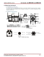
1.6 Power Wiring
The SMD23E2 and SMD24E2 accepts 24 to 48Vdc as its input power. AMCI strongly suggests using 18
AWG or larger wire for the power connections. The CNPL-2M and the CNPL-5M cables are made with 18
gauge wire, and the MS-31 connector will accept up to 18 gauge wire.
Do not apply 120 Vac to any pins of the SMD23E2 or SMD24E2. If this occurs, the unit
will be damaged and you will void the unit’s warranty.
The SMD23E2 and SMD24E2 units do not have a circuit to limit inrush current when
power is applied. If the power supply voltage is applied through the switching of con-
tacts, damage to the contacts or contact welding may occur.
Use a power supply that limits the peak output current to a value below the con-
tact switching limit.
Switch the power input to the power supply instead of the power supply’s output.
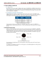
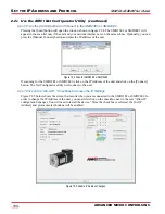
Figure T1.4 below shows how to wire power to the SMD23E2 and SMD24E2 units. Note that Pin 5, DCPow-
er
AUX
, is only used when you introduce a circuit for removing power from the motor. Colors in parentheses
are the appropriate wire color of the CNPL-5M cable.
Figure T1.4 M12 Power Wiring
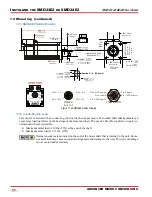
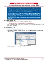
1.7 Input Wiring
Inputs 1 and 2 are single ended inputs that share the DC Common return pin. They accept 3.5 to 27 Vdc with-
out the need for an external current limiting resistor. The inputs can survive surge voltages to 35 Vdc. Figure
T1.5 below shows how to wire discrete DC sourcing and sinking sensors to inputs 1 and 2 of the SMD23E2
or SMD24E2. Colors in parentheses are the appropriate wire color of the CNPL-5M cable.
Figure T1.5 Input Wiring
+24Vdc to +48Vdc
Power Supply
+24Vdc to +48Vdc
Power Supply
Power
Control
Circuit
POWER & INPUTS
POWER & INPUTS
Pin 1: DCPower
(BRN)
MAIN
Pin 1: DCPower
(BRN)
MAIN
Pin
5: DCPower
AUX
Pin
(GRY)
5: DCPower
AUX
Pin 2: Input 1
Pin 2: Input 1
Pin
3: DC Common (BLU)
Pin
(BLU)
3: DC Common
Pin 4: Input 2
Pin 4: Input 2
Input1 or Input2
Input1 or Input2
DC Common
DC Common
+
+
+
+
–
(WHT or BLK)
(WHT or BLK)
–
5 to
24 Vdc
5 to
24 Vdc
PNP
Sourcing
Sensor
NPN
Sinking
Sensor
Out
Out
R
PULLUP
1.7.1
1.7.1
1.7.2
(BLU)
(BLU)


