20 Gear Drive, Plymouth Ind. Park, Terryville, CT 06786
Tel: (860) 585-1254 Fax: (860) 584-1973 http://www.amci.com
SMD23E2 and SMD24E2 User’s Manual
C
OMMAND
M
ODE
D
ATA
F
ORMAT
71
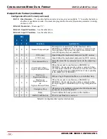
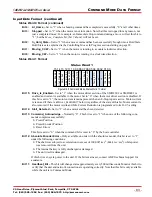
Command Word 1
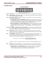
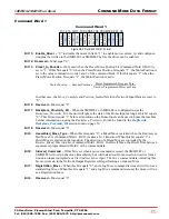
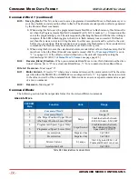
Figure R6.3 Command Word 1 Format
Bit 15: Enable_Driver –
“0” to disable the motor current, “1” to enable motor current. A valid configura-
tion must be written to the SMD23E2 or SMD24E2 before the driver can be enabled.
Bit 14: Reserved –
Must equal “0”.
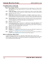
Bit 13: Preset_to_Encoder –
Only used when the Preset Motor Position bit (Command Word 0, Bit 9) is
set to “1”. If this bit equals “0” when the Preset Motor Position bit equals “1”, the Motor Position is
set to the value contained in words 2 and 3 of the command block. If this bit equals “1” when the
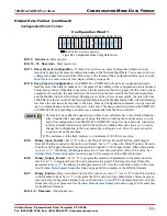
Preset Motor Position bit equals “1”, the Motor Position is set to:
In either case, the
Move_Complete
and
Position_Invalid
bits in the Network Input Data are reset to
“0”.
Bit 12: Reserved –
Must equal “0”.
Bit 11: Backplane_Proximity_Bit –
When the SMD23E2 or SMD24E2 is configured to use the
Backplace_Proximity_ Bit
, the unit will ignore the state of the Home Input as long as this bit equals
“0”. This bit must equal “1” before a transition on the Home Input can be used to home the machine.
Further information on using the
Backplace_Proximity_Bit
can be found in the
section found on page 56.
Bit 10: Reserved –
Must equal “0”.
Bit 9:
Assembled_Move_Type –
When this bit equals “0”, a Blend Move is started when the Run Assem-
bled Move bit, (Command Word 1, Bit 13) makes a 0
1 transition. When this bit equals “1”, a
Dwell Move is started on the transition. The direction of a Blend Move is controlled by the
Reverse_Blend_Direction
bit, (Command Word 1, Bit 4). In a Dwell Move, the Dwell Time between
segments is programmed in Word 9 of the command data.
Bit 8: Indexed_Command –
If this bit is set when a move command is issued, the SMD23E2 or
SMD24E2 will not run the move immediately, but will instead wait for an inactive-to-active transi-
tion on an input configured as a
Start Indexer Move
input. The move command data, including this
bit, must remain in the Network Output Registers while performing an Indexed Move.
Bit 7:
Registration_Move –
When this bit equals “0”, and a Jog Move command is issued, it will run as a
standard Jog Move. When this bit equals “1” and a Jog Move command is issued, the move will run
as a Registration Move.
Bit 6: Reserved –
Must equal “0”.
15 14 13 12 11 10 09 08 07 06 05 04 03 02 01 00
Command Word 1
En
_D
riv
er
Pr
es
et
_t
o_E
nc
R
eg
_M
ov
e
Inde
x_
Cm
d
AsM
v_
Ty
pe
R
ev
_B
le
nd
Di
r
Mo
to
r_Cur
rent
Sa
ve
_t
o_F
las
h
Motor Position
Encoder Position
Motor Programmed Steps per Turn
Encoder Programmed Pulses per Turn
-------------------------------------------------------------------------------------------
=


