background image

Advanced Energy

® 

5-28 

• 

"Changing the Interconnector" on page 5-29 

• 

"Changing the Jumpers" on page 5-32 

• 

"Reattaching the Top Cover and Reconnecting Power and R

F

' on page 5-35 

• 

Also see 

"Interaction With a Cesar Generator" on page 5-16 

for information on 

using a CESAR generator to control the V arioMatch match network 

TOOLS REQUIRED TO CHANGE THE INTERCONNECTION 

AE supplies the following equipment: 

• 

Interconnec

t

or 

•  Bridge, to hold the water tubing in place once you remove the original 

interconnector 

You will need to supply the following additional equipment: 

•  7 mm wrench 

•  12 mm wrench 

•  14 mm wrench 

DISCONNECTING POWER AND RF, AND REMOVING THE 

COVER 

To Disconnect Power and RF and to Remove the Cover: 

1. Turn off RF from the generator. 

2.  Disconnect AC 

MAINS. 

3.  Disconnect RF in 

(

RF-GENERATOR

)

4. Disconnect RF ou

(P

L

ASMA/L

O

AD

)

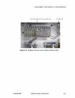
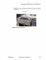
5.  Remove the top cover, being careful to not damage the plug 

l

eading to the fan: 

a.  Remove the 

l

arge top cover (with the fan) from the V arioMatch match ne

t

work 

by unscrewing the twe

l

ve screws on the cover. Leave the small top and side 

covers in place. 

b.  Disconnect the pl

ug 

leading from top lid to the fan. 

I

nsta

ll

at

i

on

Setup,  and Operat

i

on 

57020080-00D 

Summary of Contents for VarioMatch Match Network VM 1000 Platform

Page 1: ...RENO EXHIBIT 2006 Advanced Energy v Reno IPR2021 01397 AE VarioMatchTM Match Network VM 1000 1500 Platform User Manual October 2009 57020080 00D CADVANCED Ll ENERGY...

Page 2: ......

Page 3: ...User Manual AE VarioMatchTM Match Network VM 1000 1500 Platform 57020080 00D 1 C ADVANCED l ENERGY...

Page 4: ...es of whatever kind as a result of the reliance on or use of the information contained herein PRODUCT USAGE STATEMENT iv WARNING Read this entire manual and all other publications pertaining to the wo...

Page 5: ...ht license from Analog Instruments Company New Providence New Jersey 07974 VarioMatch is a trademark of Advanced Energy Industries Inc Windows NT is a registered trademark of the Microsoft Corporation...

Page 6: ...Advanced Energy vi 57020080 00D...

Page 7: ...fety Directives and Standards 1 4 Industry Guidelines 1 5 Conditions of Use 1 5 Interlocks and Limits 1 6 Chapter 2 Product Overview and Theory Product Description 2 1 Operating Modes 2 2 Theory of Op...

Page 8: ...unting the VarioMatch Match Network 5 6 Connecting the Match INTERFACE Optional 5 7 Connecting the Cooling Water 5 7 Connecting RF Input From a Generator 5 8 Connecting to the Load 5 9 Connecting the...

Page 9: ...ernal Load Checks Open Short RF Output Path 6 3 Contacting AE Global Services 6 4 Advanced Energy World Headquarters 24 x 7 Technical Support 6 4 Returning Units for Repair 6 5 Chapter 7 VarioMatch Ma...

Page 10: ...Advanced Energy X Table of Contents 57020080 00D...

Page 11: ...Environmental specifications 3 17 Table 4 1 VarioMatch match INTERFACE connector pin description 4 2 Table 4 2 Match INTERFACE switch descriptions 4 7 Table 5 1 RF input connector pin descriptions 5...

Page 12: ...Advanced Energy xii List of Tables 57020080 00D...

Page 13: ...3 N type connector 5 9 Figure 5 4 7 16 DIN female connector 5 1O Figure 5 5 MC6 connector 5 1O Figure 5 6 MC6 plug 5 10 Figure 5 7 6 mm brass tube fitting 5 11 Figure 5 8 Input Mains connector 5 12 F...

Page 14: ...tap 2 7 23 Figure 7 23 27 MHz Tune coil 6 turns tap 3 7 24 Figure 7 24 27 MHz Tune coil 6 turns tap 4 7 25 Figure 7 25 27 MHz Tune coil 6 turns tap 5 7 26 Figure 7 26 27 MHz Tune coil 6 turns tap 6 7...

Page 15: ...7 65 Figure 7 65 4 MHz Tune coil 25 turns tap 2 Load coil 4 turns tap E 7 66 Figure 7 66 4 MHz Tune coil 25 turns tap 3 Load coil 4 turns tap E 7 67 Figure 7 67 4 MHz Tune coil 25 turns tap 4 Load co...

Page 16: ...Advanced Energy 1 xvi 57020080 00D...

Page 17: ...TION BOXES IN THE MANUAL 1027 This symbol represents important notes concerning potential harm to people this unit or associated equipment Advanced Energy includes this symbol in Danger Warning and Ca...

Page 18: ...rules Do not attempt to install or operate this equipment without proper training Ensure that this unit is properly grounded see also Grounding the Unit on page 5 5 Ensure that all cables are properly...

Page 19: ...required to be in compliance with the standards and directives Product Certification Certain options of this product may be certified by CE Marking Self declaration assessed by AE Corporate Compliance...

Page 20: ...fety and EMC requirements are not violated ELECTROMAGNETIC COMPATIBILITY EMC DIRECTIVES AND STANDARDS 89 336 EEC EC Council directive on the approximation of the laws of the Member States relating to...

Page 21: ...is device in an overvoltage category II installation only Install and operate this device only with an RF generator which is installed in an overvoltage category II or better environment Install and o...

Page 22: ...roducts are notintended to meet or satisfy safety requirements Where interlocks exist you must still meet and satisfy safety requirements The presence of interlocks does notimply operator protection T...

Page 23: ...ion Some VarioMatch match networks ICP options have been optimized for inductive loads Employing vacuum variable capacitors for tuning ensures greater resistance to high voltage breakdown which often...

Page 24: ...ted in conjunction with an AE RF generator manual controls for the network are incorporated in the generator itself An additional controller is necessary only if manual operation without an AE RF gene...

Page 25: ...h network converts 100VAC to 240 VAC single phase to the DC voltages used in the match The 45 W SMPS switched mode power supply supplies 15 VDC and 5 VDC The cooling fan is powered from the 15 V suppl...

Page 26: ...ontrol board The DC bias board provides the voltage divider whereas the motor driver board buffers and rectifies the DC bias voltage so that theDC bias voltage at the interface port is always positive...

Page 27: ...atch network is modified by the installation of a variable capacitor connected in series with a fixed or tapped coil Figure 2 1 shows a typical VarioMatch L match network circuit 50Ohms RF Generator L...

Page 28: ...ity of larger than 900 pF is required The VarioMatch match network uses a load coil to extend the capacitance range of the load capacitor without the negative side effects described above For more inf...

Page 29: ...topology the tune series capacitor comes first from the generator s point of view while in configuration B L match topology the load shunt capacitor comes first Figure 2 4 Gamma topology Figure 2 5 L...

Page 30: ...Advanced Energy 2 8 Product Overview and T heory 57020080 00D...

Page 31: ...ure 3 1 through Figure 3 4 illustrate the physical dimensions The PLASMA LOAD connector can be located on either the rear panel or the bottom panel depending on your model __ _ _ _ _ _ 168 9 m m 6 65...

Page 32: ...Advanced Energy 250 96mm 9 88 21 mm 0 83 b 31 m _ m _ 5 16 Figure 3 2 VM 1000 1500platform leftside panel 3 2 Specifications 3266 57020080 00D...

Page 33: ...AE VarioMatchTM Match Network VM 1000 1500 Platform 22 50 mm 0 87 1 192 50 m 7 58 GROUND 217 50 mm 8 56 i Figure 3 3 VM 1000 1500platform rearpanel 57020080 00D Specifications 32 00 mm 1 26 3269 3 3...

Page 34: ...00 mm 9 06 14 00 mm 0 55 Holes for mountingtheunit and for ground connection ________182 00 mm_______ t 7 17 62 00 mm 2 44 Figure 3 4 VM 1000 1500platform bottompanel 3 4 Specifications 14 00 mm 0 55...

Page 35: ...k VM 1000 1500 Platform 3275 Figure 3 5 VM 1000 1500platform toppanel Spacing Requirements The following sections describethespaceneededtoprovideroomforconnections and to meet cooling requirements 570...

Page 36: ...nnector when using an angled connector For units with the PLASMA LOAD connection on the rear panel 200 mm 7 9 required for 7 16 connector when using a straight connector 80 mm 3 1 required for 7 16 co...

Page 37: ...page 5 4 Size 375 mm x 245 mm x 150 mm 14 75 X 5 9 X 9 65 Note Additional space required for air flow and connections See Spacing Requirements on page 3 5 See alsoFigure 3 1 through Figure 3 4 Weight...

Page 38: ...80 69000114 690001 16 69000226 69000227 69000228 69000229 69000230 69001214 7 16 DIN socket PN 69000001 M6 bolt PNs 69000007 69000023 69000025 69000034 69000036 69000115 69000214 69001207 MC B6N femal...

Page 39: ...9000080 14 turns taps at4 6 8 10 12 14 turns default tap setting on 3 PNs 69000004 69000018 69000022 69000023 69000024 69000025 69000034 69000046 690001 14 69000115 69000230 69000227 69000229 69001207...

Page 40: ...69000025 69000046 69000114 69000115 69000214 69000230 69000227 69000229 69000032 69000034 69001207 69001214 2 turns 3 taps default B PN 6900003 69000036 69000037 69000080 69000082 69000116 69000228 2...

Page 41: ...VDC to 10 VDC voltage Runtime from start point to end 3 seconds point Tuning range To reach appropriate resistance and reactance values you may need to change load and or tune coil settings See Set U...

Page 42: ...n tuning ranges possible for your unit see Chapter 7 VarioMatch Match Network Tuning Ranges VM1 000 Series Table 3 2 describes the VM 1000 series electrical specifications Table 3 4 Electricalspecific...

Page 43: ...g ranges possible for your unit see Chapter 7 VarioMatch Match Network Tuning Ranges VM 1 500 Series Table 3 5 describes the VM 1500 series electrical specifications Table 3 5 Electricalspecifications...

Page 44: ...2207 69002208 35 A PN 69000007 69000041 55 A Maximum RF load voltage 4000 Vpeak Input impedance to generator son Maximum load DC selfbias 0 VDC to 4000 VDC voltage DC selfbias monitor voltage 0 V to l...

Page 45: ...hat show only A after the model name or Air and Water cooled for unitsthat show W or AW after the model name Minimum water flow 1 1pm 0 26 gpm Water pressure 0 5 bar 7 25 psi differential as required...

Page 46: ...total sulfate 100 ppm total dissolved solids 250 ppm total hardness expressed as calcium carbonate equivalent maximum 250 ppm 250ppm specific resistivity of 2500 Q cm or higher at 25 C total dissolved...

Page 47: ...n ofice Air Pressure 78 kPa to 106 kPa 788 mbar to 1060 mbar Equivalent altitude 2000 m to 500 m 6562 ft to 1640 ft 78 kPa to 106 kPa 788 mbar to 1060 mbar Equivalent altitude 2000 m to 500 m 6562 ft...

Page 48: ...Advanced Energy 3 18 Specifications 57020080 00D...

Page 49: ...preset and monitoring functionality for a VarioMatch match network by an AE generator such as a CESAR It can also be used by an external controller Table 4 1 on page 4 2 describes each pin used in th...

Page 50: ...ignals are referenced to ground All inputs need to be switched to ground to activate all outputs are open collector Table 4 1 VarioMatch match INTERFACE connectorpin description Pin Return Pin 1 GND 2...

Page 51: ...ly SUPPLY For external use Maximum current draw lO0 mA 12 6 DC Output DC selfbias test voltage SELFBIAS MONITOR Provides a test voltage to monitor the DC self bias ofthe plasma electrode in the vacuum...

Page 52: ...s approximately 0 3 V representing the minimum capacity of CLoad The maximum voltage is approximately 9 7 V representing the maximum capacity of CLoad This open collector output is pulled low when the...

Page 53: ...orm User supplied circuitry may vary I I J I I I I I nGnd Figure 4 3 Pin 1O User supplied circuitry may vary Figure 4 4 Pin 11 I I v I I I I I n I Gnd Internal circuitry Internal circuitry 3441 570200...

Page 54: ...nal circuitry 10kQ 1 kQ 12 I I I I I nGnd 100 nF Figure 4 5 Pin 12 User supplied circuitry mayvary I I I I I I I 10 kQ Internal circuitry f G f100 F 21 2 4 6 I I I I n I Gnd I Figure 4 6 Pins 13 14 Co...

Page 55: ...RFACE Pin Common connection of all 5 switches Ground 1 Switch 1 motor 1 run clockwise decrease Cnme 2 Switch 2 motor 1 run counter increase Cnme 3 clockwise Switch 3 motor 2 run clockwise decrease CLo...

Page 56: ...Advanced Energy 4 8 Communication Interfaces and Controls 57020080 00D...

Page 57: ...Requirements Install this unit according tothefollowing requirements WARNING Maintenance personnel must receive propertraining before installing troubleshooting or maintaining high energy electrical e...

Page 58: ...trap connector and the ground strap See the Physical Specifications on page 3 1 to see which PLASMA LOAD connector your unit uses For water cooled units Plastic hose 6 mm OD 4 mm ID 0 24 OD 0 16 ID se...

Page 59: ...stem The following is important information for connecting to PLASMA LOAD There will be a high RF current flowing between the VarioMatch match network and the load The RF output PLASMA LOAD is much hi...

Page 60: ...d for this connection than a thick wire See the Physical Specifications on page 3 1 to see which connector your unit uses SHIELDING THE RF CONNECTIONS Shield all RF connections to prevent RF radiation...

Page 61: ...ifications on page 3 1 for dimensions and spacing requirements Ensure the unit will remain within the specified operating temperatures See Cooling Specifications on page 3 14 Ensure that exhausted air...

Page 62: ...devices Electrical shock from the VarioMatch match network cabinet To Properly Ground the VarioMatch Match Network Mount the unit as described in Mounting the VarioMatch Match Network on page 5 6 RF...

Page 63: ...ounting platewith four M6 screws Connecting the Match INTERFACE Optional The 15 pin female subminiature D connector on the front panel lets you connect the VarioMatch match network to an external remo...

Page 64: ...rotect the unit and the environment To Connect CoolingWater 1 Install the user supplied water lines to WATER IN and WATER OUT See the SERTO documentation for instructions on properly connecting the wa...

Page 65: ...ad Note VM 69000082 The RF outputconnector is customer supplied See your company s internal documentation for information The VarioMatch match network uses one ofthe following RF Output PLASMA LOAD co...

Page 66: ...igure 5 5 and Figure 5 6 on page 5 10 6 mm brass tube fitting Figure 5 7 on page 5 11 3281 Figure 5 4 7 16 DIN female connector 3277 Figure 5 5 MC6connector 19 5 mm 0 77 23 5 mm 0 93 51 5 mm 2 03 Figu...

Page 67: ...Attach the AB supplied MC6 plug to one end of auser supplied cableor copper strap Attach the plug to theMC6PLASMA LOAD output connector Attach the other end of the cable or copper strap to the load F...

Page 68: ...ting the AC MAINS cord with your input power source see Chapter 3 Specifications for the input voltage for your unit Note The VarioMatch match network does not contain an on off power switch To turn o...

Page 69: ...and appropriate response from your load 57020080 00D For example if you are using a plasma chamber look for the following a Is the plasma lit If not you may have a faulty connector or too little inpu...

Page 70: ...switch To turn on the unit connect the VarioMatch match network to the AC MAINS connector Use the AC MAINS cable appropriate for your installation 100 V to 240V at 50 Hz to 60 Hz Also read the inform...

Page 71: ...Up the Match for Your Load on page 5 16 Manual Tune Mode In addition to the automatic mode all VarioMatch match network models can be controlled manually by means of an external controller This contr...

Page 72: ...nnection to the match INTERFACE Host Port You can use the Cesar generator Host Port to control the VarioMatch match network See the Cesar generator user manual for additional information Importance of...

Page 73: ...mined by two major match components The variable capacitors The variable capacitors are determined by the VarioMatch match network model you purchased The capacitors use motors to match the load The c...

Page 74: ...e 3 7 for your unit s internal coil specifications SETTING TUNE COIL TAPS The number ofturns and available taps enables the VarioMatch match network to be flexible enough to match nearly all load syst...

Page 75: ...match network by unscrewing the twelve screws on the cover Leave the small top and side covers in place b Disconnect the plug leading from top lid to the fan 6 Using a 7 mm wrench unscrew the tap from...

Page 76: ...e wrench screw the tap to the selected tum on the coil Tune coil tap position for small capacitive load PLASMNLOAD Figure 5 9 Tapping ofthe tune coil forsmall capacitive load 5 20 Installation Setup a...

Page 77: ...chTM Match Network VM 1000 1500 Platform Tune coil tap positionformedium capacitive load PLASMNLOAD Figure 5 10 Tapping ofthe tune coilformedium capacitive load 57020080 00D Installation Setup and Ope...

Page 78: ...the Correct Tap Setting for the Load Coil 5 22 See Physical Specifications Table on page 3 7 for your unit s internal coil specifications The other device in the match network thataffects the range o...

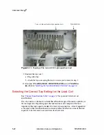
Page 79: ...on for medium size loads Use the position furthest from the load capacitor for large loads For specific recommendations contact Global Services To Change the Tap Settings on the Load Coil 1 Tum off RF...

Page 80: ...Advanced Energy Figure 5 12 Tapposition forsmall loads RFGENERATOR connection Load coil tapposition A forsmall loads 5 24 Installation Setup and Operation 57020080 00D...

Page 81: ...arioMatchTM Match Network VM 1000 1500 Platform RFGENERATOR connection 1 Load coil tap position B formedium loads Figure 5 13 Tapposition formedium loads 57020080 00D Installation Setup and Operation...

Page 82: ...fan RFGENERATOR connection Load coil tap position C for large loads b Attach the top coverusing the twelve screws you removed in step 2 9 ReconnectPLASMA LOAD RF GENERATOR and AC MAINS as described in...

Page 83: ...two different load impedance ranges By changing the capacitor s interconnection you can change the topology of the VarioMatch match network See Chapter 3 Specifications for a list of part numbers that...

Page 84: ...interconnector You will need to supply the following additional equipment 7 mm wrench 12 mm wrench 14 mm wrench DISCONNECTING POWER AND RF AND REMOVING THE COVER To Disconnect Power and RF and toRemov...

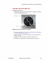
Page 85: ...igure 5 15 Alternate interconnectorand bridge 2 Disconnect water and drain the unit See Disconnecting Water and Draining the VarioMatch Match Network on page 5 38 3 Using a 12 mm wrench disconnect the...

Page 86: ...h the hole in thebridge 9 Replace thenut from the copper tube 10 Replace the compression nut from the copper tube 11 Attach the new interconnector The new interconnector attaches a On the non water su...

Page 87: ...hTM Match Network VM 1000 1500 Platform Step 8 Step 9 Step 11_ a Step 10 Figure 5 17 Attach the new interconnector 57020080 00D Installation Setup and Operation New interconnector Step 11_b bridge __...

Page 88: ...32 CHANGING THE JUMPERS To Change theJumpers 1 Removethe frontpanelby unscrewingtheelevenscrewsas shown thenremove the front panel Screws Figure 5 18 Remove the frontpanel Installation Setup and Opera...

Page 89: ...work VM 1000 1500 Platform 2 Carefully remove the three solder joints on the left box as shown and remove the top of the box Solder locations Figure 5 19 Remove solderjoints 57020080 00D Installation...

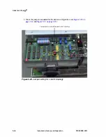
Page 90: ...s as needed for the desired configuration see Figure 5 20 on page 5 34 and Figure 5 21 on page 5 35 Twojumpersonthe left two posts for L topology Figure 5 20 Jumpersetting forLmatch topology Installat...

Page 91: ...e front panel by replacing the eleven screws REATTACHING THE TOP COVER AND RECONNECTING POWER AND RF To Reattach theTop Coverand Reconnect Powerand RF 1 Reattach the top cover a Plug in the fan b Atta...

Page 92: ...GENERATOR 4 Disconnect RF out PLASMA LOAD 5 Remove the top cover being careful to not damage the plug leading to the fan a Remove the largetop cover with thefan from the VarioMatch match network by un...

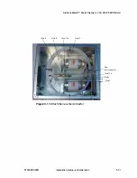
Page 93: ...he location of the circuit board andjumpers Table 5 3 Capacitance due tojumpersettings on circuitboard Bridge Capacitance J1 J2 J3 0 pF X 680pF X 1360 pF X X 2040 pF X X 2720 pF X X X 3400 pF J1 J2 Fi...

Page 94: ...g Failure to do so can result in damage to the unit during shipping Note You must evacuate the water from both the rack and from individual CESAR generators in the rack The following steps are listed...

Page 95: ...PLASMA LOAD connector For information to assist you in this procedure see Connecting to the Load on page 5 9 5 Disconnect the cooling hoses For information to assist you in this procedure see Connect...

Page 96: ...Advanced Energy 5 40 Installation Setup and Operation 57020080 00D...

Page 97: ...or warnings and resume normal operation after following these checks and procedures contact AE Global Services Troubleshooting Checklists on page 6 2 Use these checklists to begin troubleshooting your...

Page 98: ...Checks With the Power Off With PowerOff Complete theFollowing Checks 1 Ensure the power to the unit is off 2 Check for visible damage to the unit cables and connectors 3 Ensure all unit connectors ar...

Page 99: ...rkoutput connector the output cable or lead or the chamber Follow the steps below 1 Disconnect AC MAINS from both the generator and the VarioMatch match network to ensure that there is no RF power at...

Page 100: ...have the unit serial number and part number These numbers are available on unit labels Advanced Energy World Headquarters 24 x 7 Technical Support 6 4 Table 6 1 AE Global Services contactinformation O...

Page 101: ...ure instructs you to contact AE Global Services and discuss the problem with a representative Be prepared to give them the model number and serial number of the unit as well as the reason for the prop...

Page 102: ...Advanced Energy 6 6 Troubleshooting and Global Services 57020080 00D...

Page 103: ...nd tap settings of the load and tune coils of your unit see Physical Specifications Table on page 3 7 14 TURN TUNE SERIES COIL Schematic The tune series coil has taps at4 6 8 10 12 and 14 turns These...

Page 104: ...Coil Tap Setting Tap Setting A B C 1 Figure 7 2 Figure 7 8 Figure 7 14 2 Figure 7 3 Figure 7 9 Figure 7 15 3 Figure 7 4 Figure 7 10 Figure 7 16 4 Figure 7 5 Figure 7 1 1 Figure 7 17 5 Figure 7 6 Figu...

Page 105: ...AE VarioMatchTM Match Network VM 1000 1500 Platform Figure 7 2 Tune coil 14 turns tap 1 Load coil 3 turns tap A 57020080 00D VarioMatch Match Network Tuning Ranges 7 3...

Page 106: ...Advanced Energy Figure 7 3 Tune coil 14 turns tap2 Load coil 3 turns tap A 7 4 VarioMatch Match Network Tuning Ranges 57020080 00D...

Page 107: ...AE VarioMatchTM Match Network VM 1000 1500 Platform Figure 7 4 Tune coil 14 turns tap 3 Load coil 3 turns tap A 57020080 00D VarioMatch Match Network Tuning Ranges 7 5...

Page 108: ...Advanced Energy Figure 7 5 Tune coil 14 turns tap 4 Load coil 3 turns tap A 7 6 VarioMatch Match Network Tuning Ranges 57020080 00D...

Page 109: ...AE VarioMatchTM Match Network VM 1000 1500 Platform Figure 7 6 Tune coil 14 turns tap 5 Load coil 3 turns tap A 57020080 00D VarioMatch Match Network Tuning Ranges 7 7...

Page 110: ...Advanced Energy Figure 7 7 Tune coil 14 turns tap 6 Load coil 3 turns tap A 7 8 VarioMatch Match Network Tuning Ranges 57020080 00D...

Page 111: ...AE VarioMatchTM Match Network VM 1000 1500 Platform Figure 7 8 Tune coil 14 turns tap 1 Load coil 3 turns tap B 57020080 00D VarioMatch Match Network Tuning Ranges 7 9...

Page 112: ...Advanced Energy Figure 7 9 Tune coil 14 turns tap2 Load coil 3 turns tap B 7 10 VarioMatch Match Network Tuning Ranges 57020080 00D...

Page 113: ...AE VarioMatchTM Match Network VM 1000 1500 Platform Figure 7 10 Tune coil 14 turns tap 3 Load coil 3 turns tap B 57020080 00D VarioMatch Match Network Tuning Ranges 7 11...

Page 114: ...Advanced Energy Figure 7 11 Tune coil 14 turns tap 4 Load coil 3 turns tap B 7 12 VarioMatch Match Network Tuning Ranges 57020080 00D...

Page 115: ...AE VarioMatchTM Match Network VM 1000 1500 Platform Figure 7 12 Tune coil 14 turns tap 5 Load coil 3 turns tap B 57020080 00D VarioMatch Match Network Tuning Ranges 7 13...

Page 116: ...Advanced Energy Figure 7 13 Tune coil 14 turns tap 6 Load coil 3 turns tap B 7 14 VarioMatch Match Network Tuning Ranges 57020080 00D...

Page 117: ...AE VarioMatchTM Match Network VM 1000 1500 Platform Figure 7 14 Tune coil 14 turns tap 1 Load coil 3 turns tap C 57020080 00D VarioMatch Match Network Tuning Ranges 7 15...

Page 118: ...Advanced Energy Figure 7 15 Tune coil 14 turns tap2 Load coil 3 turns tap C 7 16 VarioMatch Match Network Tuning Ranges 57020080 00D...

Page 119: ...AE VarioMatchTM Match Network VM 1000 1500 Platform Figure 7 16 Tune coil 14 turns tap 3 Load coil 3 turns tap C 57020080 00D VarioMatch Match Network Tuning Ranges 7 17...

Page 120: ...Advanced Energy Figure 7 17 Tune coil 14 turns tap 4 Load coil 3 turns tap C 7 18 VarioMatch Match Network Tuning Ranges 57020080 00D...

Page 121: ...AE VarioMatchTM Match Network VM 1000 1500 Platform Figure 7 18 Tune coil 14 turns tap 5 Load coil 3 turns tap C 57020080 00D VarioMatch Match Network Tuning Ranges 7 19...

Page 122: ...Advanced Energy Figure 7 19 Tune coil 14 turns tap 6 Load coil 3 turns tap C 7 20 VarioMatch Match Network Tuning Ranges 57020080 00D...

Page 123: ...500 coilandinductorschematic 6turncoil Smith Charts T able 7 2 Location ofSmith chartillustrations for6 turn tune coil Tune Coil VarioMatch Frequency Tap Setting 27 MHz 40 MHz 1 Figure 7 21 Figure 7 2...

Page 124: ...Advanced Energy 27 MHZ UNITS Figure 7 21 27MHz Tune coil 6 turns tap 1 7 22 VarioMatch Match Network Tuning Ranges 57020080 00D...

Page 125: ...AE VarioMatchTM Match Network VM 1000 1500 Platform Figure 7 22 27 MHz Tune coil 6 turns tap 2 57020080 00D VarioMatch Match Network Tuning Ranges 7 23...

Page 126: ...Advanced Energy Figure 7 23 27 MHz Tune coil 6 turns tap 3 7 24 VarioMatch Match Network Tuning Ranges 57020080 00D...

Page 127: ...AE VarioMatchTM Match Network VM 1000 1500 Platform Figure 7 24 27 MHz Tune coil 6 turns tap 4 57020080 00D VarioMatch Match Network Tuning Ranges 7 25...

Page 128: ...Advanced Energy Figure 7 25 27 MHz Tune coil 6 turns tap 5 7 26 VarioMatch Match Network Tuning Ranges 57020080 00D...

Page 129: ...AE VarioMatchTM Match Network VM 1000 1500 Platform Figure 7 26 27 MHz Tune coil 6 turns tap 6 57020080 00D VarioMatch Match Network Tuning Ranges 7 27...

Page 130: ...Advanced Energy 40 MHZ UNITS Figure 7 27 40 MHz Tune coil 6 turns tap 1 7 28 VarioMatch Match Network Tuning Ranges 57020080 00D...

Page 131: ...AE VarioMatchTM Match Network VM 1000 1500 Platform Figure 7 28 40 MHz Tune coil 6 turns tap 2 57020080 00D VarioMatch Match Network Tuning Ranges 7 29...

Page 132: ...Advanced Energy Figure 7 29 40 MHz Tune coil 6 turns tap 3 7 30 VarioMatch Match Network Tuning Ranges 57020080 00D...

Page 133: ...AE VarioMatchTM Match Network VM 1000 1500 Platform Figure 7 30 40 MHz Tune coil 6 turns tap 4 57020080 00D VarioMatch Match Network Tuning Ranges 7 31...

Page 134: ...Advanced Energy Figure 7 31 40 MHz Tune coil 6 turns tap 5 7 32 VarioMatch Match Network Tuning Ranges 57020080 00D...

Page 135: ...0415 Schematic The tune series coil has taps at taps at 10 13 16 19 22 and 25 turns These are labeled 1 through 6 in the schematic The load shunt coil has 4 turns with 5 taps labeled A B C D and E Th...

Page 136: ...orthe2 MHz VM4015 show the tuning range withtune coil tap set at 6 load coil tap set at E The tune range varies by capacitance setting T able 7 3 Location ofSmith chartillustrations for2 MHz VM0415 Ca...

Page 137: ...AE VarioMatchTM Match Network VM 1000 1500 Platform Figure 7 34 2 MHz Tune coil 6 Load coil E OpF 57020080 00D VarioMatch Match Network Tuning Ranges 7 35...

Page 138: ...Advanced Energy Figure 7 35 2 MHz Tune coil 6 Load coil E 680 pF 7 36 VarioMatch Match Network Tuning Ranges 57020080 00D...

Page 139: ...AE VarioMatchTM Match Network VM 1000 1500 Platform Figure 7 36 2 MHz Tune coil 6 Load coil E 1360pF 57020080 00D VarioMatch Match Network Tuning Ranges 7 37...

Page 140: ...Advanced Energy Figure 7 37 2 MHz Tune coil 6 Load coil E 2040pF 7 38 VarioMatch Match Network Tuning Ranges 57020080 00D...

Page 141: ...AE VarioMatchTM Match Network VM 1000 1500 Platform Figure 7 38 2 MHz Tune coil 6 Load coil E 2720pF 57020080 00D VarioMatch Match Network Tuning Ranges 7 39...

Page 142: ...oil tap setting AE does not recommend varying the additional capacitance setting Table 7 4 Location ofSmith for4 MHz VM 0415 Tune Coil Load Coil Tap Setting Tap Setting A B C D E 1 Figure 7 40 Figure...

Page 143: ...42 Figure 7 48 Figure 7 54 Figure 7 60 Figure 7 66 4 Figure 7 43 Figure 7 49 Figure 7 55 Figure 7 61 Figure 7 67 5 Figure 7 44 Figure 7 50 Figure 7 56 Figure 7 62 Figure 7 68 6 Figure 7 45 Figure 7 5...

Page 144: ...Advanced Energy Figure 7 41 4 MHz Tune coil 25 turns tap 2 Load coil 4 turns tap A 7 42 VarioMatch Match Network Tuning Ranges 57020080 00D...

Page 145: ...AE VarioMatchTM Match Network VM 1000 1500 Platform Figure 7 42 4 MHz Tune coil 25 turns tap 3 Load coil 4 turns tapA 57020080 00D VarioMatch Match Network Tuning Ranges 7 43...

Page 146: ...Advanced Energy Figure 7 43 4 MHz Tune coil 25 turns tap 4 Load coil 4 turns tap A 7 44 VarioMatch Match Network Tuning Ranges 57020080 00D...

Page 147: ...AE VarioMatchTM Match Network VM 1000 1500 Platform Figure 7 44 4 MHz Tune coil 25 turns tap 5 Load coil 4 turns tap A 57020080 00D VarioMatch Match Network Tuning Ranges 7 45...

Page 148: ...Advanced Energy Figure 7 45 4 MHz Tune coil 25 turns tap 6 Load coil 4 turns tap A 7 46 VarioMatch Match Network Tuning Ranges 57020080 00D...

Page 149: ...AE VarioMatchTM Match Network VM 1000 1500 Platform Figure 7 46 4 MHz Tune coil 25 turns tap 1 Load coil 4 turns tap B 57020080 00D VarioMatch Match Network Tuning Ranges 7 47...

Page 150: ...Advanced Energy Figure 7 47 4 MHz Tune coil 25 turns tap 2 Load coil 4 turns tap B 7 48 VarioMatch Match Network Tuning Ranges 57020080 00D...

Page 151: ...AE VarioMatchTM Match Network VM 1000 1500 Platform Figure 7 48 4 MHz Tune coil 25 turns tap 3 Load coil 4 turns tap B 57020080 00D VarioMatch Match Network Tuning Ranges 7 49...

Page 152: ...Advanced Energy Figure 7 49 4 MHz Tune coil 25 turns tap 4 Load coil 4 turns tap B 7 50 VarioMatch Match Network Tuning Ranges 57020080 00D...

Page 153: ...AE VarioMatchTM Match Network VM 1000 1500 Platform Figure 7 50 4 MHz Tune coil 25 turns tap 5 Load coil 4 turns tap B 57020080 00D VarioMatch Match Network Tuning Ranges 7 51...

Page 154: ...Advanced Energy Figure 7 51 4 MHz Tune coil 25 turns tap 6 Load coil 4 turns tap B 7 52 VarioMatch Match Network Tuning Ranges 57020080 00D...

Page 155: ...AE VarioMatchTM Match Network VM 1000 1500 Platform Figure 7 52 4 MHz Tune coil 25 turns tap 1 Load coil 4 turns tap C 57020080 00D VarioMatch Match Network Tuning Ranges 7 53...

Page 156: ...Advanced Energy Figure 7 53 4 MHz Tune coil 25 turns tap 2 Load coil 4 turns tap C 7 54 VarioMatch Match Network Tuning Ranges 57020080 00D...

Page 157: ...AE VarioMatchTM Match Network VM 1000 1500 Platform Figure 7 54 4 MHz Tune coil 25 turns tap 3 Load coil 4 turns tap C 57020080 00D VarioMatch Match Network Tuning Ranges 7 55...

Page 158: ...Advanced Energy Figure 7 55 4 MHz Tune coil 25 turns tap 4 Load coil 4 turns tap C 7 56 VarioMatch Match Network Tuning Ranges 57020080 00D...

Page 159: ...AE VarioMatchTM Match Network VM 1000 1500 Platform Figure 7 56 4 MHz Tune coil 25 turns tap 5 Load coil 4 turns tap C 57020080 00D VarioMatch Match Network Tuning Ranges 7 57...

Page 160: ...Advanced Energy Figure 7 57 4 MHz Tune coil 25 turns tap 6 Load coil 4 turns tap C 7 58 VarioMatch Match Network Tuning Ranges 57020080 00D...

Page 161: ...AE VarioMatchTM Match Network VM 1000 1500 Platform Figure 7 58 4 MHz Tune coil 25 turns tap 1 Load coil 4 turns tap D 57020080 00D VarioMatch Match Network Tuning Ranges 7 59...

Page 162: ...Advanced Energy Figure 7 59 4 MHz Tune coil 25 turns tap 2 Load coil 4 turns tap D 7 60 VarioMatch Match Network Tuning Ranges 57020080 00D...

Page 163: ...AE VarioMatchTM Match Network VM 1000 1500 Platform Figure 7 60 4 MHz Tune coil 25 turns tap 3 Load coil 4 turns tap D 57020080 00D VarioMatch Match Network Tuning Ranges 7 61...

Page 164: ...Advanced Energy Figure 7 61 4 MHz Tune coil 25 turns tap 4 Load coil 4 turns tap D 7 62 VarioMatch Match Network Tuning Ranges 57020080 00D...

Page 165: ...AE VarioMatchTM Match Network VM 1000 1500 Platform Figure 7 62 4 MHz Tune coil 25 turns tap 5 Load coil 4 turns tap D 57020080 00D VarioMatch Match Network Tuning Ranges 7 63...

Page 166: ...Advanced Energy Figure 7 63 4 MHz Tune coil 25 turns tap 6 Load coil 4 turns tap D 7 64 VarioMatch Match Network Tuning Ranges 57020080 00D...

Page 167: ...AE VarioMatchTM Match Network VM 1000 1500 Platform Figure 7 64 4 MHz Tune coil 25 turns tap 1 Load coil 4 turns tap E 57020080 00D VarioMatch Match Network Tuning Ranges 7 65...

Page 168: ...Advanced Energy Figure 7 65 4 MHz Tune coil 25 turns tap 2 Load coil 4 turns tap E 7 66 VarioMatch Match Network Tuning Ranges 57020080 00D...

Page 169: ...AE VarioMatchTM Match Network VM 1000 1500 Platform Figure 7 66 4 MHz Tune coil 25 turns tap 3 Load coil 4 turns tap E 57020080 00D VarioMatch Match Network Tuning Ranges 7 67...

Page 170: ...Advanced Energy Figure 7 67 4 MHz Tune coil 25 turns tap 4 Load coil 4 turns tap E 7 68 VarioMatch Match Network Tuning Ranges 57020080 00D...

Page 171: ...AE VarioMatchTM Match Network VM 1000 1500 Platform Figure 7 68 4 MHz Tune coil 25 turns tap 5 Load coil 4 turns tap E 57020080 00D VarioMatch Match Network Tuning Ranges 7 69...

Page 172: ...Advanced Energy Figure 7 69 4 MHz Tune coil 25 turns tap 6 Load coil 4 turns tap E 7 70 VarioMatch Match Network Tuning Ranges 57020080 00D...

Page 173: ...Platform ICP Schematics Cselies RF IN RF OUT Cslnmt Figure 7 70 GP coil and inductorschematic Gamma RF IN Liu wire Csbunt Cseiies RF OUT Figure 7 71 GP coil and inductorschematic L match 57020080 00D...

Page 174: ...Advanced Energy Smith Charts Figure 7 72 VM 1500 Gamma 7 72 VarioMatch Match Network Tuning Ranges 57020080 00D...

Page 175: ...AE VarioMatchTM Match Network VM 1000 1500 Platform Figure 7 73 VM 1500 L match 57020080 00D VarioMatch Match Network Tuning Ranges 7 73...

Page 176: ...Advanced Energy Figure 7 74 VM4015 Gamma 7 74 VarioMatch Match Network Tuning Ranges 57020080 00D...

Page 177: ...chTM Match Network VM 1000 1500 Platform DELTA MATCH Schematic RF IN Lin Cseries wire Cshunt Lout Figure 7 75 Delta match coilandinductorschematic 57020080 00D VarioMatch Match Network Tuning Ranges R...

Page 178: ...Advanced Energy Smith Chart Figure 7 76 Tune coil 2 5 turns VM PN 69000082 Schematic and Smith charts are not available 7 76 VarioMatch Match Network Tuning Ranges 57020080 00D...

Page 179: ...C j 99 26 5 hum IT Q RF OUI Loni Figure 7 77 VM 700coilandinductorschematic Smith Chart The Smith charts in this manual show the tuning only at tap A on the load coil Although the tuning differs for t...

Page 180: ...tillustrations for VM 700 Tune Coil Load Coil Tap Setting Tap Setting A 7 Figure 7 84 8 Figure 7 85 9 Figure 7 86 10 Figure 7 87 Figure 7 78 Tune coil 10 turns tap 1 Load coil 3 turns tap A 7 78 Vario...

Page 181: ...AE VarioMatchTM Match Network VM 1000 1500 Platform Figure 7 79 Tune coil 10 turns tap2 Load coil 3 turns tap A 57020080 00D VarioMatch Match Network Tuning Ranges 7 79...

Page 182: ...Advanced Energy Figure 7 80 Tune coil 1O turns tap 3 Load coil 3 turns tap A 7 80 VarioMatch Match Network Tuning Ranges 57020080 00D...

Page 183: ...AE VarioMatchTM Match Network VM 1000 1500 Platform Figure 7 81 Tune coil 1O turns tap 4 Loadcoil 3 turns tapA 57020080 00D VarioMatch Match Network Tuning Ranges 7 81...

Page 184: ...Advanced Energy Figure 7 82 Tune coil 1O turns tap5 Loadcoil 3 turns tapA 7 82 VarioMatch Match Network Tuning Ranges 57020080 00D...

Page 185: ...AE VarioMatchTM Match Network VM 1000 1500 Platform Figure 7 83 Tune coil 1O turns tap 6 Load coil 3 turns tap A 57020080 00D VarioMatch Match Network Tuning Ranges 7 83...

Page 186: ...Advanced Energy Figure 7 84 Tune coil 1O turns tap 7 Load coil 3 turns tap A 7 84 VarioMatch Match Network Tuning Ranges 57020080 00D...

Page 187: ...AE VarioMatchTM Match Network VM 1000 1500 Platform Figure 7 85 Tune coil 10 turns tap 8 Load coil 3 turns tap A 57020080 00D VarioMatch Match Network Tuning Ranges 7 85...

Page 188: ...Advanced Energy Figure 7 86 Tune coil 1O turns tap 9 Load coil 3 turns tap A 7 86 VarioMatch Match Network Tuning Ranges 57020080 00D...

Page 189: ...AE VarioMatchTM Match Network VM 1000 1500 Platform Figure 7 87 Tune coil 10 turns tap 10 Loadcoil 3 turns tap A 57020080 00D VarioMatch Match Network Tuning Ranges 7 87...

Page 190: ...Advanced Energy 7 88 VarioMatch Match Network Tuning Ranges 57020080 00D...

Page 191: ...3 1O specifications 3 8 3 9 3 10 tune 2 4 2 5 compliance directives and standards 1 4 unit 1 3 conditions of use 1 5 connecting AC input 5 11 57020080 00D CESAR generator 4 1 cooling water 5 7 ground...

Page 192: ...22 set up the match 5 16 load checks troubleshooting 6 3 M MAINS seealsoAC input connector 3 8 5 12 manual tuning mode 5 15 marking CE 1 3 maximum load DC selfbias voltage 3 11 3 12 3 13 3 14 maximum...

Page 193: ...er 3 11 3 12 3 13 mounting 3 7 overvoltage category 3 17 physical 3 1 3 7 PLASMA LOAD connector 3 8 pollution degree 3 17 RF input connector 3 7 runtime 3 11 3 12 3 13 3 14 size 3 7 spacing requiremen...

Page 194: ...3 11 3 12 3 13 warranty authorized returns 6 5 water connecting 5 7 connectors 3 8 contaminants specification 3 16 flow specification 3 15 hose specificatinos 5 2 pressure specification 3 15 temperat...

Reviews: