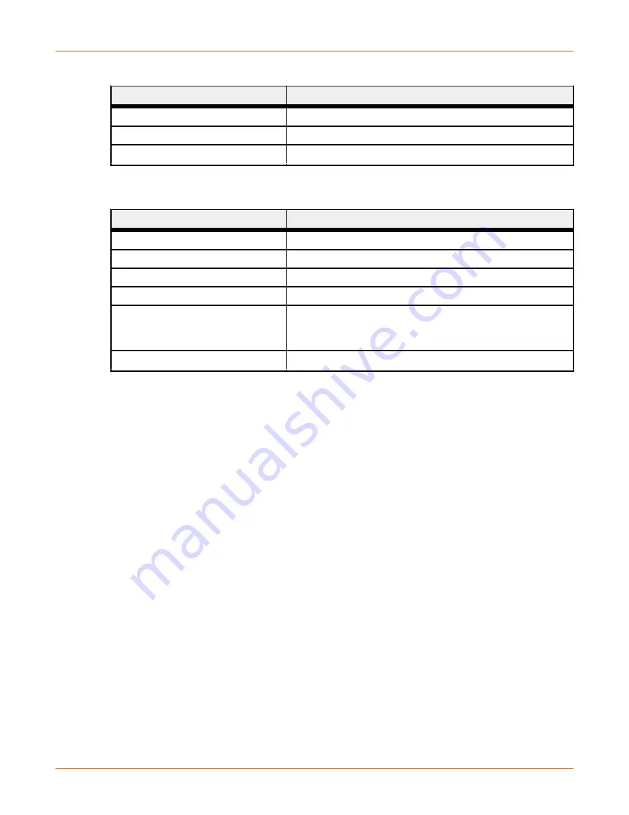
Table 3. Link/activity LED (Continued)
LED State
Description
Green, flickering
100 Mbit/s activity
Yellow
10 Mbit/s link established
Yellow, flickering
10 Mbit/s activity
Table 4. RJ-45 Ethernet pinout
Pin
Description
1
TD+
2
TX-
3
RX+
6
RX-
4, 5, 7, 8
Normally left unused; to ensure signal integrity, these pins
are tied together and terminated to PE via a filter circuit in
the module.
Housing
Cable shield
CONFIGURING WITH THYRO-TOOL PRO PC
SOFTWARE
You can configure the Thyro-PX power controller using either the Thyro-Tool Pro PC software or the
Thyro
‑
Touch display.
To configure the unit, you will:
• Adapt the Thyro-PX hardware configuration
If required, you can also:
• Select the configuration
• Configure the diagnostics
• Configure the flexible link parameters
Adapting Thyro-PX Hardware Configuration
Open parameter file with the unit online in the
Port Explorer
tab of the Thyro-Tool Pro PC software,
or use the Thyro
‑
Touch display.
Set the Anybus module slot to
Modbus TCP
in the Thyro-PX device hardware configuration:
Advanced Energy
®
Thyro-PX
™
Anybus
®
Modbus TCP
57010166-00A
Thyro-PX
™
Anybus
®
Modbus TCP
3


