Appendix C. System Configuration Charts
61200.076L2-1
TSU 600 User Manual
111
Appendix C
System Configuration Charts
This appendix contains five steps/tables to support
the chapter,
Example Operations
. It is recommended
that these tables be copied and used as work sheets
when configuring the system.
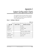
Step 1: Configure Network
Table C-A
Control Pin Connection Configuration Chart for Network Interface
MENU ITEM
SELECTION USED
SELECTIONS AVAILABLE
1)FORMAT
D4, ESF*
2)CODE
AMI, B8ZS*
3)YEL ALARM
ENABLE*, DISABLE
4)XMIT PRM
ON, OFF*
5)TIMING MODE
NETWK* (NI), INTERNAL, BASE DTE,
SECONDARY INTERFACE, NORMAL
6)LINE BUILD
0dB*, 7.5dB, -15dB, -22.5dB, AUTO
7)INBAND LOOPBK
ACCEPT*, REJECT
8)BIT STUFFING
DISA*, ENA
*= Factory Default
Summary of Contents for TSU 600
Page 1: ...61200 076L2 1B July 1997 TSU 600 USER MANUAL Part Number 1200076L2 1200076L2 DC...
Page 4: ...Table of Contents...
Page 96: ...Chapter 3 Operation 84 TSU 600 User Manual 61200 076L2 1...
Page 118: ...Chapter 4 Example Operations 106 TSU 600 User Manual 61200 076L2 1...
Page 126: ...Appendix C System Configuration Charts 114 TSU 600 User Manual 61200 076L2 1...
Page 128: ...Appendix D TSU 600 System Messages 116 TSU 600 User Manual 61200 076L1 1...


