Network Management Connections
61181001L1-5E
23
NETWORK MANAGEMENT CONNECTIONS
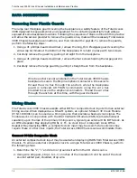
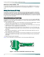
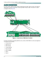
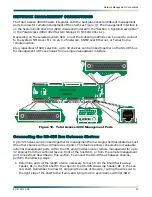
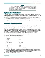
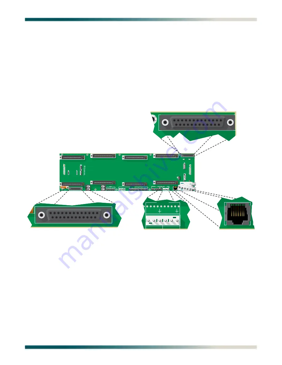
The Total Access 3000 Chassis integrates onto the backplane several different management
ports to allow for remote management of the shelf, see
. The management interface is
on the System Controller Unit (SCU) discussed in detail in the “Section 1, System Description”
in the Total Access 3000/3010 System Manual, P/N 61181001L1-1).
Depending on the selected system SCU, one of the following methods can be used to connect
to the system: NMA over TL1 on an X.25 network, SNMP over Ethernet, or Telnet from a
remote location.
Also, regardless of SCU selection, up to 32 shelves can be linked together on the RS-485 bus
for management of those shelves from a single management interface.
Figure 10. Total Access 3000 Management Ports
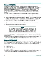
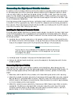
Connecting the RS-485 Bus Between Shelves
Up to 32 shelves can be linked together for management from a single shelf designated as host
(the other shelves will be configured as clients). This feature allows conservation of valuable
external management ports within the CO, and provides local or remote management for up to
32 shelves from the craft interface on front of the host SCU, or from the remote management
port connections described in this section. To connect the RS-485 bus between shelves,
perform the following steps:
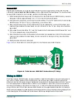
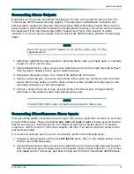
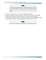
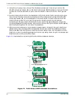
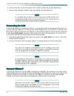
1. Determine and cut the length of wire necessary to reach from the RS-485 wire-wrap
header,
P2
, in the first shelf in the chain to the RS-485 wire-wrap header,
P2
, in the sec-
ond shelf. Remember to allow for stripping the ends of the wire, routing the wires out to
the right side of the shelf to the frame, and tying down in accordance with CO SOP.
E D C B A
D C B A
F2
LOOP
TEST
ACCESS
33
1
64
32
33
1
64
32
33
1
64
32
33
1
64
64
32
ADMIN
J31
PAIR 2
P11
P12
P8
PAIR 3
PAIR 1
33
1
64
32
P10
PAIR 8
PAIR 6
PAIR 5
P9
P7
J33
EXTCLK
64
33
1
33
20
20
20
10
20
PAIR 7
1
10
20
32
1
64
32
33
1
NTWK MGMT
J30
-48 VDC PRI
-48 VDC
RET
P22
ACO
RMT
AUX1
AUX2
A
A
A
A
B
B
B
B
-48 VDC SEC
-48 VDC RET
P3
NO
NC
C
NO
NC
C
AUX1
AUX2
P21
CRI-A
NO C NC NO C NC NO C NC
MAJ-A
MIN-A
P1
P20
P2
J32
P19
P18
ALARM OUTPUTS
CRI-A
B - OUT
NO C NC NO C NC NO C NC
MAJ-A
MIN-A
A - OUT
B IN
E - NET
IN
OUT
+ –
+ – S
+ – S
+ – S
RS485
A B
A B
T
R
S
T1
R1
S
F1
10
30
20
40
48
E D C B A
P14
P15
S
S
30
40
48
1
6
T
R
T1
R1
P23
DSX1
TEST
ACCESS
F4
F3
PC2A 94V-0
2298
1
J1
S
1
R22
P24
EXTCLK
C-IN
1
10
20
8
+
–
R21
CUSTOM
TELECOM
E190349
1181004L1
PAIR 4
P5
Total Access
Chassis
NTWK MGMT
J30
ADMIN
J31
E D C B A
J32
E - NET
P2
IN
OUT
RS485
A B
A B

