


Total Access 3000 23-Inch Chassis Installation and Maintenance Practice
22
61181001L1-5E
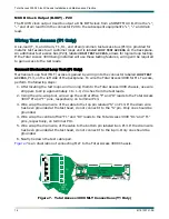
NOTE
Omit step 2 if the alarmed piece of equipment has its own source of
–48 VDC and does not need the –48 VDC feed from the Total
Access 3000 chassis. The Total Access 3000 chassis expects to see
–48 VDC on pin
A
of the alarm pair when an alarm condition
exists.
3. Using wire strippers, strip 1 to 2 inches from both ends of the wire.
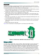
4. Using a wire-wrap gun, wire wrap one wire to the
B
pin of the Total Access 3000
AUX1
header (P22), and the other end to the alarmed unit alarm terminal marked “B.”
5. Wire wrap one end of the second wire to the
A
pin of the Total Access 3000 Chassis
AUX1
header (
P22
) and the other end to the appropriate equipment alarm terminal.
NOTE
Check with the equipment manufacturer for exact alarm markings.