Total Access 3000 23-Inch Chassis Installation and Maintenance Practice
18
61181001L1-5E
Wiring to MDF (TDM)
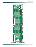
The Total Access 3000 delivers services out to the customer loops via 64-pin amphenol
connectors on the Total Access 3000 Chassis backplane in the same manner that it receives
its DSX-1 input from the DSX cross-connect panel. The one exception to this rule is the
delivery of optical fiber froma fiber based access module. Deploying either HDSLx or T1
requires the connection of two amphenol connectors. To take maximum advantage of
ADTRAN’s capability to deliver ISDN out to the customer, five amphenol connectors are
required.
To connect amphenol connectors to the Total Access 3000, perform the following steps:
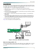
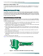
1. Noting the orientation of the backplane male connection receptacle, push the female cable
connector onto the backplane connector.
2. Using a small straight-slot-head screwdriver, snug the screw on the right side of the cable
connector into the hole provided on the backplane connector. Secure the connector into
place on the left side by tightening the wire tie around the body of the cable connector.
3. Using a side cutter, snip the wire tie end off flush with the barrel of the tie.
4. Repeat steps 1-4 for each connector on the backplane being used for the intended
application.
5. Neatly tie off the data cables to the left of the shelf.
NOTE
All data cables should exit the Total Access 3000 Chassis to the left
(as viewed from the rear), and be neatly tied to the frame as per CO
SOP. Other wiring (i.e., power, loop test access, clock, external
alarms, etc.) can exit either right or left and be tied off to the frame.
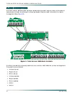
The ground wire, attached to
J33
on the backplane, should be routed to the nearest suitable
grounding point.
Refer to the Installation and Maintenance Practices for the access modules being deployed, for
a full description of the different Total Access 3000 loop assignments and pinouts.
Wiring to MDF (DSLAM)
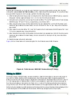
The Total Access 3000 Chassis is designed to be a DSLAM as well as a TDM platform. With the
use of a Cell Switch Module or Ethernet Switch Module in Slot A and/or Slot B and multiport
access modules, the Total Access 3000 can deploy up to the following number of circuits:
• 14 DS3 circuits
• 28 OC-3c circuits
• 112 DSX or E1 circuits
• 224 xDSL circuits
Refer to the Installation and Maintenance Practices for the access modules being deployed, for
a full description of the different Total Access 3000 loop assignments and pinouts.

