ADT A-ADRP16E-320 User Manual Download Page 76

User’s Manual 

Pressing the 

SEQUENCE

 button will cause the cameras to display sequentially on the monitor. 

When in one of the multi-view formats, pressing this button will cause the DVR to through 
user-defined screen layouts (page sequence), or the bottom, right screen to display live cameras 
sequentially (cameo sequence).  Selecting another display mode, or pressing the 

SEQUENCE


button again will exit the Sequence mode.  When in one of the multi-view formats, pressing the 

Left

 or 

Right

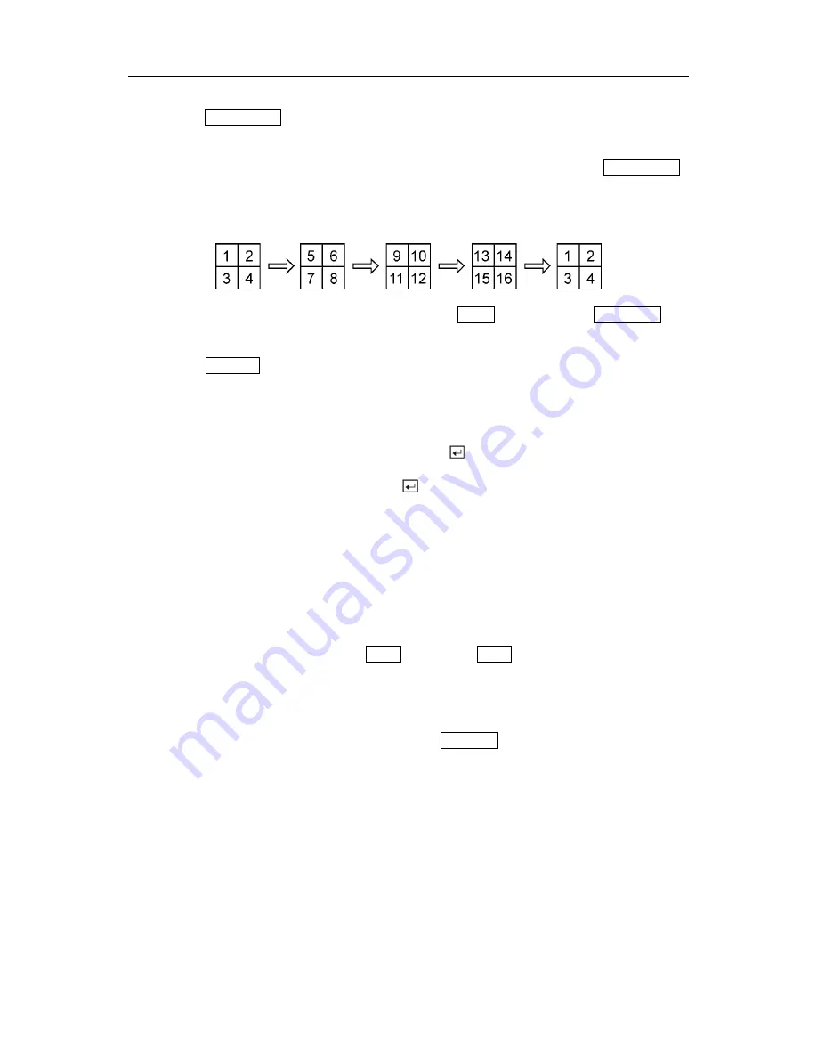
 arrow buttons will cause the DVR to go to the previous or the next page.  For 

example, if you press the 

Right

 arrow button in 4x4 format, the DVR changes the page like that. 


For the sequence display on the spot monitor, press the 

SPOT

 button and then 

SQUENCE


button. 
 
Pressing the 

FREEZE

 button will freeze the current image on the screen until you press the 

button again. 
 

Active Cameo Mode 


You can enter the Active Cameo mode by pressing the 

 button in any multi-view format.  The 

gray-highlight box at the bottom of video indicates the active cameo, and pressing the arrow 
buttons moves the active cameo.  Pressing the 

 button while in the Active Cameo mode exits 

the Active Cameo mode.  The active cameo mode will keep up 15 seconds if there is no 
consequent operation.  
 
In active cameo mode, press the camera button you want to show that video at active cameo. 
After setting the camera number at active cameo, the DVR moves the active cameo to the next 
cameo.  You can change the screen layout in this way.  
 
The active cameo also can be used to select the camera to control Pan, Tilt and Zoom 
capabilities and select the audio channel to communicate.  If you want to select the audio 
channel in active cameo mode, press the 

TALK

 button.  The 

TALK

 button LED will be lit and the 

camera channel in a cameo window will be the audio channel. 
 

PIP Mode 


You can display a Picture-in-Picture by pressing the 

DISPLAY

 button.  You can change the 

location of the PIP by pressing the 

Up

 and 

Down

 arrow buttons and its size by pressing the 

Left


and 

Right

 arrow buttons. 


66 

Summary of Contents for A-ADRP16E-320

Page 1: ...A ADRP4E 120 A ADRP9E 240 A ADRP16E 320 Digital Video Recorders...

Page 2: ...User s Manual ii...

Page 3: ...THIS INFORMATION TO YOUR TELEPHONE COMPANY THIS EQUIPMENT IS DESIGNED TO BE CONNECTED TO THE TELEPHONE NETWORK OR PREMISES WIRING USING A COMPATIBLE MODULAR JACK WHICH IS PART 68 COMPLIANT THE REN IS...

Page 4: ...ment C If the equipment has been exposed to rain or water D If the equipment does not operate normally by following the operating instructions adjust only those controls that are covered by the operat...

Page 5: ...6 GND Ground 6 AO 1 TO 4 Alarm Out 6 ARI Alarm Reset In 6 Connecting to the RS485 7 Connecting to the Network Port 7 Connecting to the Modem Port 7 Connecting to the USB Port 8 Connecting to the Ultra...

Page 6: ...n 28 Configuring Input Devices 28 Camera Setup Screen 29 Alarm In Setup Screen 30 Motion Detector 31 Alarm Out Setup Screen 33 Audio Setup Screen 35 RS232 RS485 Setup Screen 36 Configuring Recording S...

Page 7: ...Callback Center Setup Screen 57 Password Setup Screen 58 Config Screen 60 Archive 60 Clip Copy 62 Load Default Setup 64 Clear All Data 64 Chapter 4 Operation 65 Turning on the Power 65 Live Monitoring...

Page 8: ...75 Preparing the USB IDE hard disk drive in Windows 98 75 Appendix B Reviewing Backup Clip Images 77 Appendix C Troubleshooting 79 Appendix D Connector Pin Outs 80 I O Connector Pin Outs 80 RS485 Con...

Page 9: ...System Information screen 18 Figure 26 System Information Change screen 19 Figure 27 Virtual keyboard 19 Figure 28 System Upgrade screen 20 Figure 29 Date Time setup screen 21 Figure 30 Holiday Setup...

Page 10: ...p screen 53 Figure 63 Network Setup screen 54 Figure 64 LAN Setup screen 55 Figure 65 Modem Setup screen 56 Figure 66 Callback Center Setup screen 57 Figure 67 Password setup screen 59 Figure 68 Confi...

Page 11: ...ords up to 60 NTSC Images per Second 50 PAL Images per Second Loop Through Video Connectors Continuous Recording in Disk Overwrite Mode Front Panel Displays Time Date Recording Mode and Remaining Stor...

Page 12: ...iew video after selecting the time or event Your DVR can be set up for event or time lapse recording You can define times to record and the schedule can change for different days of the week and user...

Page 13: ...er s Manual Rack mount Kit Assembly Screws for Adding Hard Disk Drives BNC Cable SVHS Cable and RJ 11 Telephone Modem Cable Required Installation Tools No special tools are required to install the DVR...

Page 14: ...connectors 1 Connect the coaxial cables from the video sources to the BNC Video In connectors Figure 5 Video input connectors 2 Connect the RJ 11 cables from the observation cameras to the modular RJ...

Page 15: ...simultaneous operation Connecting Audio NOTE It is the user s responsibility to determine if local laws and regulations permit recording audio Figure 8 Audio In and Out connectors Your DVR can record...

Page 16: ...s can be wired to the AI Alarm In and GND Ground connectors The threshold voltage is 4 3V and should be stable at least 0 5 seconds to be detected See Chapter 3 Configuration for configuring alarm inp...

Page 17: ...half duplex serial communications signals The RS485 connector can also be used to control PTZ pan tilt zoom cameras Connect RX TX and RX TX of the control system to the TX RX and TX RX respectively o...

Page 18: ...ith the hard disk drive to connect it to the DVR Connecting to the Ultra Wide SCSI Port Figure 16 SCSI connector A SCSI port is provided to connect external storage devices for recording or archiving...

Page 19: ...e 18 Factory reset switch The DVR has a Factory Reset switch under the RS232 connector This switch will only be used on the rare occasions that you want to return all the settings to the original fact...

Page 20: ...nt accidental power loss Be sure to slide the release away from the socket before removing the plug WARNING ROUTE POWER CORDS SO THAT THEY ARE NOT A TRIPPING HAZARD MAKE CERTAIN THE POWER CORD WILL NO...

Page 21: ...up your DVR and for daily operations Up Down Left Right Arrow Buttons These buttons are used to navigate through menus and GUI They are also used to control Pan and Tilt when in the PTZ mode The arrow...

Page 22: ...rom the DVR s built in microphone to an optional intercom The user can select the audio channel While in the full screen mode the camera channel on the screen will be the audio channel you are using W...

Page 23: ...menu Pressing the button again will exit the Search menu This operation can be user password protected Zooms In in PTZ mode PLAY PAUSE Button Pressing the PLAY PAUSE button plays back images at regul...

Page 24: ...ed Turning the ring clockwise plays video forward Turning the ring counterclockwise plays video backward Playback speed varies with the amount the ring is turned The playback speeds are x0 5 x0 5 and...

Page 25: ...displaying the time of the recording REMAIN displays when the digits are displaying the remaining hard disk drive capacity ALARM displays when any camera is in the event driven recording mode The bel...

Page 26: ...nd date display language camera audio remote control record mode network and password Your DVR can be set up using various screens and dialog boxes Press the MENU button to enter the setup screens The...

Page 27: ...f NOTE It is the user s responsibility to determine if local laws and regulations permit recording audio Highlight the box beside Sequence Dwell Time and select from 3 to 60 seconds for the camera seq...

Page 28: ...e setup screen If the Quick Setup screen appears turn it off as described above The Normal Setup screen gives you access to all the DVR s setup screens System Information Highlight System Information...

Page 29: ...the button That character appears in the title bar and the cursor moves to the next position Pressing toggles between the upper and lower case keyboards backspaces and deletes entered characters You...

Page 30: ...e the software only in the System Information Change screen To upgrade the software connect the USB device containing the upgrade package file to the DVR Highlight Upgrade and press the button The Sys...

Page 31: ...e button Highlight the second box beside Date Time and press the button The individual sections of the time will highlight Use the Up and Down arrow buttons to change the number Use the Left and Right...

Page 32: ...ar should be updated once the current year s holiday has passed Figure 30 Holiday Setup screen You can save your changes by highlighting OK and pressing the button Selecting Cancel exits the screen wi...

Page 33: ...ed If you want to synchronize the time instantly highlight the Now button and press the button CAUTION When selecting Now any video with a later time and date will be lost if the time and date of a ti...

Page 34: ...dition if it does not detect any recording or if there is an alarm during the designated time Highlight the box under the Interval heading and press the button A slide bar appears allowing you to set...

Page 35: ...M A R T Alert High Temperature or Not installed depending on storage conditions Good The storage condition is normal Bad Data cannot be written on or read from the storage device S M A R T Not work S...

Page 36: ...lems by activating an internal buzzer or external alarms and or notifying a remote site Highlight the box beside Storage Problem Action Alarm Out Notify and press the button to select from Beep the al...

Page 37: ...n Selecting Cancel exits the screen without saving the changes System Log Screen Highlight System Log in the Main menu and press the button The System Log screen appears Figure 35 System Log screen Th...

Page 38: ...is shuts the DVR down When shutting down the DVR you need to confirm that you want to shut down the unit and you will be asked for an administrator password Configuring Input Devices You can configure...

Page 39: ...from On Off Covert 1 or Covert 2 NOTE When set to Covert 1 the DVR displays the camera title and status icons on the covert video When set to Covert 2 the DVR displays only the camera title on the co...

Page 40: ...up Screen Highlight Alarm In in the Main menu and press the button The Alarm In setup screen appears Figure 39 Alarm In setup screen The alarm terminal strip on the back of the DVR has inputs associat...

Page 41: ...must be activated to trigger a motion alarm Highlight a box under the Min Size heading and adjust the number The smaller the number fewer detection blocks must be activated and therefore more sensiti...

Page 42: ...s one block at a time in groups of 4 9 or 16 individual block groups 4 9 and 16 channel DVR respectively A block group is positioned within the image area using the Up and Down arrow buttons and indiv...

Page 43: ...nactive blocks and deactivates active blocks Exit Zone Setup Asks you to confirm changes and then returns to the previous screen Alarm Out Setup Screen The Alarm Out setup screen allows you to establi...

Page 44: ...week or Holiday on the left of the screen Select an entire block of time by highlighting the time at the top of the screen Select the entire screen by highlighting the empty box in the upper left cor...

Page 45: ...n it is On the DVR will NOT play live or recorded audio Highlight the box beside Audio In and press the button A drop down menu displays the audio inputs Mic In Line In and Observation NOTE Mic In is...

Page 46: ...ct the correct Baud Rate Parity Data Bits and Stop Bits for the device you are connecting to the DVR For RS232 it is possible to select either Remote Control or External Modem or in the Usage field Fo...

Page 47: ...is full and stop recording Record Mode Setup Screen Figure 47 Record Mode Setup screen Highlight the Record Resolution box and select from High and Standard All other variables being equal Selecting...

Page 48: ...l be kept from 1 to 99 Days You can save your changes by highlighting OK and pressing the button Selecting Cancel exits the screen without saving the changes Time Lapse Record Mode Setup Screen Figure...

Page 49: ...only during certain times based on time day of the week and holidays The smallest time segment you can use is 30 minutes A blue rectangle indicates the DVR is set to record during those 30 minutes Wh...

Page 50: ...sible to have it record images before the event occurs The Pre Event Record screen allows you to define how to handle pre event recording You can turn individual cameras On or Off for pre event record...

Page 51: ...time is chosen to closely match the total expected event length the number of events listed in the Event Log will be reduced What happens when the event is longer than the dwell time If an event is si...

Page 52: ...as described earlier Highlight the Camera box and press the button A camera selection screen appears Select the camera number you would like to associate with the sensor NOTE You can associate multipl...

Page 53: ...box and press the button A schedule screen appears Set the schedule as described earlier Highlight the Alarm Out box and either Beep or the alarm output terminal that you want to associate with the s...

Page 54: ...re 53 Alarm In Event Action Notify setup screen Highlight the Sched box and press the button A schedule screen appears Set the schedule as described earlier Highlight the Notify box and press the butt...

Page 55: ...chedule as described earlier Highlight the Camera box and press the button A camera selection screen appears Select the camera number you would like to associate with the camera NOTE You can associate...

Page 56: ...hed box and press the button A schedule screen appears Set the schedule as described earlier Highlight the Alarm Out box and either Beep or the alarm output terminal that you want to associate with th...

Page 57: ...ted Figure 56 Motion Detector Event Action Notify setup screen Highlight the Sched box and press the button A schedule screen appears Set the schedule as described earlier Highlight the Notify box and...

Page 58: ...ule as described earlier Highlight the Camera box and press the button A camera selection screen appears Select the camera number you would like to associate with the camera that has lost video NOTE Y...

Page 59: ...internal buzzer or external alarms Figure 58 Video Loss Event Action Alarm Out setup screen Highlight the Sched box and press the button A schedule screen appears Set the schedule as described earlie...

Page 60: ...Loss Event Action Notify setup screen Highlight the Sched box and press the button A schedule screen appears Set the schedule as described earlier Highlight the Notify box and press the button This t...

Page 61: ...beside Date and press the button to toggle the date display On and Off Highlight the box beside Time and press the button to toggle the time display On and Off Highlight the box beside Title and pres...

Page 62: ...screen layouts pages In the Cameo mode the bottom right window in a multi screen format sequences through all cameras NOTE The DVR does not sequence the camera having video loss in the Cameo mode You...

Page 63: ...time for each camera displayed on the spot monitor You can also turn event monitoring on and off Figure 62 Spot Monitoring Setup screen Highlight the box beside Sequence Dwell Time and press the butto...

Page 64: ...d Then you can enter a new password you will be asked to confirm the new password before it is accepted NOTE These passwords are for network use They are different from the Admin and User passwords fo...

Page 65: ...ing speed of 60 NTSC images per second 50 PAL images per second The number of remote site RAS connected to the DVR does not affect the recording speed It will be affected by only Transfer Speed The lo...

Page 66: ...rt number for two different programs otherwise the DVR cannot be connected with a PC running RAS CAUTION When changing the IP port settings you must change the IP port settings on a PC running RAS as...

Page 67: ...e button Selecting Cancel exits the screen without saving the changes NOTE An internal modem may have compatibility problem with the modem used for the RAS Remote Administration System Please contact...

Page 68: ...digit number The first three digits are the site ID number and the last digit is the type of event 1 Alarm In 2 Motion Detection 3 Video Loss and 10 Storage For example 0753 means that Site 75 has lo...

Page 69: ...asking you to enter a new password using the camera buttons After you press the button another screen appears asking you to confirm the new password NOTE The Admin and User passwords are composed of...

Page 70: ...ions such as switching between Quick Setup and Normal Setup archiving and backing up video loading default setup and clearing all data Figure 68 Config screen Archive The Archive screen can be used to...

Page 71: ...the DVR stops archiving when the device drive is full Highlight the box beside Auto Archive and press the button This toggles between On and Off When it is On the DVR will archive video automatically...

Page 72: ...op button will display only during archiving NOTE If you have a large quantity of recorded video to archive either stop recording or reset the recording speed The oldest data to be archived might be o...

Page 73: ...n four SCSI hard disk drives are connected NOTE A CD R or CD RW disk that was written to using a computer might not work in a USB CD RW drive connected to the DVR You can define how much video to back...

Page 74: ...HE EXTERNAL DRIVE COULD BE DAMAGED and you will get an error message the next time you try to back up You will need to power down the DVR and restart it to get rid of the error message Once the file s...

Page 75: ...to initialize While it is initializing the DVR will display HELLO Then the HELLO will start moving to the left Live Monitoring As soon as the DVR completes its initialization process it will begin sho...

Page 76: ...sing the button in any multi view format The gray highlight box at the bottom of video indicates the active cameo and pressing the arrow buttons moves the active cameo Pressing the button while in the...

Page 77: ...the PLAY PAUSE button to zoom out You can use the RW and FF buttons to focus the image Figure 73 PTZ Preset screen Figure 74 Preset view screen You can save camera position settings as presets so tha...

Page 78: ...e unit is ready to record The red REC on the display will light and a red dot appears on the monitor when the clock reaches a scheduled recording time and the DVR starts recording video Recording Audi...

Page 79: ...le Ring The Shuttle Ring only functions in the Playback mode The Shuttle Ring is spring loaded and returns to the center position when released Turning the ring clockwise plays video forward Turning t...

Page 80: ...ore details Calendar Search Searches using a calendar see below for more details Event Search Selects video from the event log see below for more details NOTE The searching speed might decrease while...

Page 81: ...button You can use the Left and Right arrow buttons to highlight the hour minutes and seconds Use the Up and Down arrow buttons to change to the time you want to search for video Once you have entere...

Page 82: ...s NOT mean video was recorded for the entire hour Once you have set the date and time you want to search highlight the GO button and press the button The selected date and time will display The PLAY P...

Page 83: ...w search condition Figure 80 Event Search by Camera screen Figure 81 Event Search by Event screen Highlight the box beside Search by and press the button to toggle between Camera and Event You can sea...

Page 84: ...nt options When you select the Search by Event select event options for each device Once you set your desired search conditions highlight Search and press the button to display the search results in t...

Page 85: ...nd follow the instructions on the screen Make sure that the FAT32 is selected for the file system NOTE The partition size should be less than 32GB because of Microsoft limitations After formatting is...

Page 86: ...OS Partition And Type Y to use all available space and hit the enter key Hit ESC to exit the screen after the USB IDE hard disk drive partition is created 11 Restart your computer and verify the newly...

Page 87: ...with very high image quality will be played back slowly Figure 82 Player screen Click the Save button to save the current image in a bitmap file format to the local hard disk drive or floppy disk Cli...

Page 88: ...ing the mouse and dragging along the slide bar The Brightness Revert Button reloads to the original image The Brightness Control Slide Bar adjusts the brightness of the backup images by clicking the m...

Page 89: ...ters such as schedule and events defined during configuration Red REC LED indicates the DVR is ready to record DVR has stopped recording If hard disk drive is full you will either need to delete video...

Page 90: ...tor Pin Outs I O Connector Pin Outs AI 1 to 16 Alarm Inputs 1 to 16 GND Chassis Ground 4 connectors AO 1 to 4 Alarm Outputs 1 to 4 ARI Alarm Reset In RS485 Connector Pin Outs Master Unit Slave Unit RX...

Page 91: ...Digital Video Recorder Observation Camera Connector Pin Outs Pin 1 Alarm Input Pin 2 15VDC Output Pin 3 Intercom Audio Output Pin 4 Video Input Pin 5 Intercom Audio Input Pin 6 Ground 81...

Page 92: ...User s Manual Appendix E Map of Screens 82...

Page 93: ...TSC 50ips PAL INPUTS OUTPUTS Alarm Input 4 9 or 16 TTL NC NO programmable 4 3V threshold selectable from terminal inputs or camera alarm inputs Alarm Output 4 TTL open collector 5mA 12V 30mA 5V Alarm...

Page 94: ...y Storage EIDE hard disk drive up to 2 Backup Storage UltraWide SCSI hard disk drive RAID Built in CD RW drive USB hard disk drive or CD RW drive GENERAL Dimensions W x H x D 16 9 x 3 5 x 14 0 430mm x...

Reviews: