background image

SEt


loads or saves a custom set-up or power up default. Press the select key to initiate the menu

function. Press the left or right arrow key to display 

SEt

. Press the up or down key to scroll thru

(LOAd, Save), press select, press the up or down key to scroll thru the settings (1 – 6).  Press the
select key to load or are save the setting.  Setting #1 is loaded when the machine is powered up.
(see also factory and custom set-up section) 

The 

set

 menu item has 2 sub-menus:

Load- 

loads a setup.

To load a setting


:

Press select

Press left or right arrow until 

SET

 menu is displayed. 

Press up or down arrow to display 

Load

.

Press select

Press up or down arrow to display the number of the setting you want to

load (1-6)

Press select.

Save- 

saves a customized setting.

To save a setting:

Adjust force, speed, acceleration as needed. 

Press select 

Press left or right arrow until SET menu is displayed. 

Press up or down arrow to display Save.

Press select

Press up or down arrow to display the number of the setting you want to

customize (1-6) (# 1 is the setting that is loaded on power up.)

Press select.

The display will blink FFFF, and then return back to your setting.  

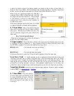
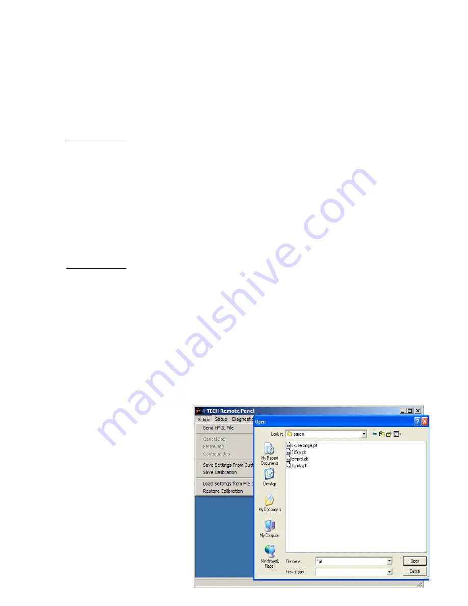
Remote Panel

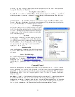
The Remote Panel program is used
to   address   all   i-TECH   CUTTER
functions.     It   is   loaded   onto   the
computer that is directly connected
to   the   i-TECH   CUTTER   by   the
installation   cd.     The   installation
program   places   a   shortcut   on   the
Windows Desktop so that you can
easily   start   the   program   when
needed.     It   can   be   run   in   the
background   with   most   cad
programs. 

14

Summary of Contents for i-TECH 230

Page 1: ...OPERATOR S MMC i TECH CUTTER MANUAL Manual Date August 2010 for build 12 F or later Copyright 2006 10 Allen Datagraph Systems LLC All Rights reserved http www allendatagraph com ...

Page 2: ...4 Load Media 4 Setting Force Velocity 4 Sending Job 4 Illustrator CorelDraw 4 AllenCAD 5 Omega Composer 5 Signlab 5 Flexisign 5 Operation of the i TECH SmartMarkTM System 5 Optional SmartMarkTM Sensor 5 Setting Up Your Label Job 5 Explanation of SmartMarkTM 6 Types of SmartMarkTM Scanning 6 Designing Labels 7 Planning Label 7 Using Adobe Suite Tools 7 Using Corel Suite Tools 8 Lining up SmartMarkT...

Page 3: ...Menu 16 State Tab 16 State Tab Advance Options 16 Pen Control Tab 17 Rubber Tab 17 Rubber Tab Advanced Options 17 Line Sensor 18 Line Sensor Advanced Options 19 Skew Tab 19 Skew Tab Advanced Options 20 Scale Tab 20 Scale Tab Advanced Options 20 Settings Menu 21 Settings Menu Advanced Options 22 Options Menu 23 Options menu Advance Options 24 Dynamic Force Adjust Advanced Option 24 Diagnostics 25 W...

Page 4: ... Lower Continuous 37 32 Lift Lower Demand 38 32 PWM Amplifier Status 32 Read Calibration Constants 32 Reed Switch 24 33 Front Panel Only Diagnostics 33 Display Last Error 15 33 Factory Defaults 43 33 Set Model Number 03 33 Set Static DHCP IP Address 04 33 Trouble Shooting 34 Error Codes 39 Appendix A Installation And Assembly Instructions 39 Appendix B SmartMarkTM Setup 39 Appendix C Loading 39 Ap...

Page 5: ...I equipment please bear in mind that troubleshooting of complex electronic equipment can sometimes take multiple attempts to repair an issue It is always best from a manufacturer s point of view to have the complete system in house to insure that the machine is in perfect working order when you receive it back from us Please consider all aspects before making your decision as to which option to ut...

Page 6: ...on warranty parts are required to be paid in full prior to shipment Technical Support Up to 4 hours of call in technical support is available at no charge during the warranty period Technical support is available during business hours based on Eastern Time Monday thru Friday Technical support outside the limits stated will be billed at current rates For Technical support call 603 216 6344 There ar...

Page 7: ...st version http adsi usa com techsupport cutterdriver html Then download and install the remote panel program from this page http adsi usa com techsupport i TECHfirmware html If you are using AllenCAD you may download latest version from http adsi usa com techsupport AllenCAD html To download other Technical support bulletins go to http adsi usa com click on tech support then online documents Find...

Page 8: ... use force up down buttons and velocity 66 use velocity up down buttons Press test cut button This draws the test cut Use joy stick arrows to move carriage away from cut area If you cut through backer reduce force If you cannot weed me dia increase force If material slips between grit roller and pinch wheels use slower accelerations Spring pressure can also be changed by using alter nate springs s...

Page 9: ...opy Click send Operation of the i TECH SmartMarkTM System Optional SmartMarkTM Sensor The SmartMarkTM option that is available for Allen i TECH cutters is an optical registration system that allows cutting of pre printed graphics The SmatMark system has the capability of recognizing up to three registration marks and adjusting for scale and skew discrepancies the may occur The SmartMarkTM option c...

Page 10: ... next frame to be within the scan distance of the end of the frame The Red LED pointer must be manually positioned with the joystick buttons at the approximate 0 0 coordinate position prior to sending the first job The SmartMark system automatically reposi tions the sensor for subsequent copies The positioning process must be repeated if the joystick buttons are used This is helpful because it all...

Page 11: ...ronment archive 2 there is this duck that i have lunch with Right click on the image and save it Using Adobe Suite Tools Open photoshop and crop magic wand and trim using laso tool to erase water near duck No need to be real accurate as we will create a cut line that trims the duck the way we want it to appear save image as duck no water jpg Use image size change height of image to 10 This makes t...

Page 12: ...path edit tools Add 1 2 inch rectangles for origin and scale on the dielines layer The targets must be in same place on print and dielines layers These rectangles should have strokes and not filled This completed label file is at this link Web Site Copy CD Copy Use File save to save the file on your hard drive as big duck ai Using a color printer print im age To send dielines to cutter click on di...

Page 13: ...le tool Draw small rectangle of any size near where you want it Change size of rectangle to 0 5 0 5 while rectangle is selected Zoom in to target only Move target so that left and bottom of target are touching guide lines Repeat for lower right intersection placing target so that right and bottom of target are touching guide lines Lock the print layer so you don t accidentally move it during editi...

Page 14: ...e upper right Select rotation from none 90 180 or 270 Cutting label After you have set the properties click OK to close proper ty window Then click on the Cut button to send the job to the cutter Smart Mark Setup See calibration procedure at Web Site Copy CD Copy available on the technical support page of the Allen Datagraph web site at http www allendatagraph com tech support smart mark cutter Sm...

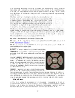
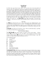
Page 15: ...rce up button Hold the key down and the numbers will start moving slowing then more quickly Press the down arrow key to lower the number Alternatively the force keys will increment the single digits and the speed keys will increment the 10 s digits If you enter 0 the copy will stop at end of next job If you enter 001 then it will count up forever Remember the number displayed includes the first co...

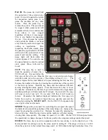
Page 16: ...is used to perform SmartmarkTM operations on identical sheets Web Size Copy CD Copy F3 This key is a short cut to the OPER mode It is equivalent to pressing select left right until OPEr is displayed and pressing select RESET the cutter by pressing the F1 F2 and F3 keys in order JOYSTICK The joystick is used for positioning the knife and media in the die cutting station and for several other functi...

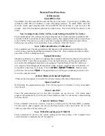
Page 17: ...isplayed press the select key The display will read 0001 The number represents the number of inches or centimeters to be metered in the x axis Increase the number by pressing the up arrow key of the joystick Hold the key down and the numbers will start moving slowing then more quickly Press the down arrow key to lower the number Alternatively the force keys will increment the single digits and the...

Page 18: ...ay the number of the setting you want to load 1 6 Press select Save saves a customized setting To save a setting Adjust force speed acceleration as needed Press select Press left or right arrow until SET menu is displayed Press up or down arrow to display Save Press select Press up or down arrow to display the number of the setting you want to customize 1 6 1 is the setting that is loaded on power...

Page 19: ...his command will locate the firmware file and send it to the i TECH Turn off your equipment Press the load button on your front panel and then turn on the Allen Datagraph equipment to be upgraded Start the Remote Panel by clicking on start program Allen Datagraph Remote Panel Click on Setup Com Port and verify that the cor rect port has a check next to its name Click on Action Upload Firmware If a...

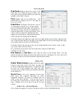
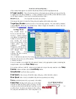
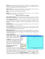
Page 20: ...receive a cut file The Pause radio button means the cutter is currently paused and the Ready button means the cutter is loaded and ready to receive the cut file and proceed with cutting This set of buttons duplicates the Load and Pause buttons on the front panel The Mode radio butons sets the operation Select cutting pen plotting drawing or pouncing The i TECH will normally only use the Cut functi...

Page 21: ... low the corners will be rounded and the circles will have nicks In that case try an offset of 0 014 or more If a good test pattern cannot be achieved in this manor inspect the knife blade and replace as necessary Hole Distance and Tear Size are used when the cutter is in the Pounce Mode The hole distance setting is the distance between holes and the tear size is the distance the cutter moves with...

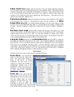
Page 22: ... or slow cutting This parameter works like a curve smoothing algorithm and is used to improve poor HPGL files Anticipation Rubber default 0 001 and Anticipation Vinyl default 0 0004 is a parameter that adjusts the backlash compensation in the cutter The Anticipation Rubber is the parameter used when the cutter is in tangential emulation mode and the Anticipation Vinyl is the parameter used when no...

Page 23: ... move between jobs is the distance after the farthest excursion of the x axis during a frame that the i TECH should advance to find the target in the next frame of labels This item is duplicated in the DirectCut printer driver as the space between jobs These two parameters are added together so if the printer driver is normally used Set this parameter to 0 Line Sensor Advanced Options This menu it...

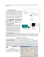
Page 24: ...e skew target when the 2nd parameter of the FO command is 1 This command is used on CAD systems that do not emit the FO HPGL command You set up the initialization string to have BJ1 FO 1 1 for origin skew and scale processing or BJ1 FO0 1 for origin and skew processing This causes the cutter to look at the Y Target Location parameter from this menu item Scan Skew Point A fourth scanning mode is im...

Page 25: ...trol panel See key command summary Changes to a Set Up unless saved will be in effect only until changed from the control panel CAS software the unit is turned off or reloaded Any of the features shown in the Setup Form may be saved to one of the systems 6 memory locations To save a custom set up simply fill in the desired value s in the appropriate window including the Setup Number click on the S...

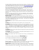
Page 26: ... distance between holes when the cutter is used in the pounce mode Tear Size displays and sets the hole size created when the cutter is in the pounce mode Acceleration displays and sets the servo acceleration The unit of measurement is 1 4 g s or 8 feet per second per second This parameter is more important in small graphics than in large labels or text Use a setting of 1 for heavy material and 2 ...

Page 27: ...ipped with the Long X coordinate system in all factory set ups and is compatible with most cutter or printer drivers The choice of coordinate systems other than Long X is beyond the scope of this document Options Menu The options menu displays and sets the following parameters Auto Origin Offset determines whether moving the joystick automatically sets the origin to 0 0 Most CAD systems and the Al...

Page 28: ...0 If set to low force pot range is 0 50 This allows higher resolution for low forces If set to high force pot range is 0 100 This must be set to high if you need more than 250 grams of force High Resolution Force sets the force resolution to 1 to 1000 steps instead of 1 to 100 steps It is useful when cutting very hard to cut medias It allow setting the force between two of the standard force setti...

Page 29: ...ional diagnostics are available if advanced menus are used Window In user operation only terminal mode is useful Some advance diagnostics use a chart to display data This menu allows changing between chart and terminal data Help About display software version of remote panel The firmware version of the cutter is displayed on the main menu Putting a check next to enable debug log displays the commu...

Page 30: ...m or by calling 603 216 6344 H20 017 30 Allen Datagraph i TECH DFS Centra Axxis cutting blade Ideal for label stock Angle of blade at 30 degrees to have exact control on depth of cut This blade has a 0 012 inch 0 0305 cm offset It can be identified by its blue plastic cap H20 007 45 Allen Datagraph i TECH DFS Centra Axxis cutting blade Ideal for general pur pose cutting of vinyl and other thin mat...

Page 31: ...gularity with which the cutter needs to be cleaned is dependent on the usage as well as the climate and contaminants in the cutter s environment It is recommended that the following cleaning steps be done at least as often as indicated for each procedure 1 Biweekly Clean the three grit wheel surfaces with a stiff bristled e g tooth not wire brush to remove any media particles that may have built u...

Page 32: ... remove the pods at either end of the i TECH This can be done by removing about 16 screws along the edge of the pod covers You can operate the cutter with pods installed in the extended position by reinstalling the pods using two screws see also TSB Mechanical Adjustments to Restore Cut Quality Website Copy CD Copy Y Axis The Y axis short belt runs between the Y axis servomotor and a gear assembly...

Page 33: ...e when a key is pressed The fail safe system is designed to detect failures in the operation of the electromechanical system in the cutter and to prevent such failures from causing other damage The cutter monitors motor currents and will generate an error if motor current too high or unmeasureable It also generates an error for impossible or dangerous conditions The appropriate error code will app...

Page 34: ...draw a 10 inch square Default Calibration 08 diagnostic sets the calibration constants back to the factory defaults prior to initial calibration Af ter running this diagnostic you will have to either restore the calibration constants or rerun the cali bration procedure described in Website Copy CD Copy available on the technical support page of the Allen Datagraph web site at http www allendatagra...

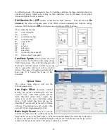
Page 35: ...ured and the size of the media will be assumed to be proportional to the width measured A test pattern will then be plotted With 230 315 front panel press copy copy test cut to start confidence test With membrane panel from the front panel scroll to 0002 press the Select Key The i TECH will start by sensing the media width and then will draw a sample file From the remote panel click on Confidence ...

Page 36: ...e configured with media present sensors They detect the presence of media If they detect media a 1111 is displayed on the front panel If they do not detect media 0000 is display If your cutter has paper sensors they will be mounted just below the oval holes in the platen on the right side of the cutter The paper dust must be removed from windows of sensors in order for sen sor to work correctly LE...

Page 37: ...s to 192 168 4 2 If you are using a dhcp server most algorithms normally try to assign same ip address to mac address everytime the device requests an ip address If you have trouble with your dhcp server giving you a different ip address everytime you turn on your machine you can set a static ip address To run diagnostic on 230 or 315 you type esc z e g press esc key then period key then z key to ...

Page 38: ...until just enough knife blade is exposed to cut through the media but not the backer Test by drawing knife across media by hand You can then use a higher force with no cut through It is important that the groove filler be installed fully and evenly otherwise material cut through may occur in some sections across the cutter Insufficient backer weight Check mechanical adjustments Website Copy CD Cop...

Page 39: ...target and background with no stray marks that could be seen as targets Verify printer properties are correct Rotation is set correctly Target cut should be in same corner on preview as selected origin corner Find origin property is set to Origin only or other advanced op tion Verify sensor settings have not been lost in the remote panel se lect setup line sensor menu Verify x sensor offset is abo...

Page 40: ...ADER box click preferences button No action when you send data to cutter Allen Spooler If plot is sent from computer and cutter doesn t cut check for Allen spooler in the task bar Lower right of monitor green box with red arrow near time If it is not there go to start button programs all programs startup allen spooler and click on allen spooler If you get message saying allen spooler starting with...

Page 41: ...rol panel If the cutter initial izes there is no need to look further If this does not solve the problem proceed to the next step Open rear cover turn cutter on and observe the belt attached to the motor If the motor pulley continues to turn then the short motor belt is most likely either loose or worn out Carefully in spect the teeth on the belt for wear with the machine off The pulley can be rot...

Page 42: ... Inspect pinch wheels Clean grit wheel and pinch wheels Reduce acceleration and or velocity Change springs Web Site Copy or CD Copy 38 ...

Page 43: ... codes are in the following linked doc ument Web Site Copy CD Copy You can recognize the mmc machines by looking at the communication port If your port looks like this use this link to error codes Appendix A Installation And Assembly Instructions Website Copy CD Copy Appendix B SmartMarkTM Setup Website Copy CD Copy Appendix C Loading Model 230 Website Copy CD Copy Model 315 Website Copy CD Copy M...

Page 44: ...ence in which case the user will be required to correct the interference at his own expense In order to maintain compliance with FCC regulations shielded cables must be used with this equipment Operation with non approved equipment or unshielded cables is likely to result in in terference to radio television reception This device complies with part 15 of FCC Rules Operation is subject to the follo...

Reviews: