


FR
FR
EN
FIELD TEST DEVICE - sigfox Europe - Guide utilisateur / User guide version V1.1.3
35
Page
of 47
3. SCREEN DESCRIPTION
The LCD screen of the product is split on few part :
• The START screen (Showing the firmware version) - Only on the powering up
• The SIGFOX CYCLE screen
• The GPS screen
• The PER screen (Packet Error Rate)
• The DOWNLINK FRAME screen
The following icon are present on each screen of the product
Item
Icon
Description
GPS status
(First on the left)
No icon
GPS has been deactivated
GPS has not been synchronized
GPS has been synchronized
Temperature
(Third on the left)
Temperature in °C
Battery
(Last on the left)
Battery level
Product in charge
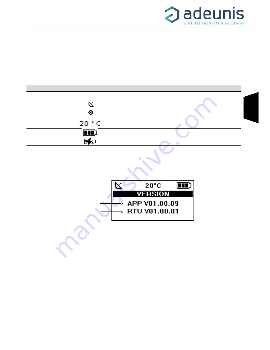
3.1. Start Screen
The device is switched on using the ON/OFF switch located on the underside of the device. Once it has been switched on, the device’s LCD screen
will light up and the start menu will be displayed. This screen show the 2 firmware versions during few seconds.
NOTE :
If the device does not switch on, this could mean that there is insufficient battery charge. You would then need to connect the device to
a USB charger. When the battery is completely empty, it is possible that the device will not switch on, even when connected. Please wait a few
minutes before the device can be used.
3.2. Screen Cycle sigfox
This screen is displayed after the start screen.
All the frame transmit or receive on the network can be see on the screen. If the product is correctly set, frames are directly sending on the
sigfox network as soon as the product is power on. The periodic transmission icon and 3 sending frames sigfox cycle information (UL1 to UL3)
must appear, join the emission frequency.
Uplink and Downlink transmission information will be displayed on the LCD screen.
The first line show the Uplink information «ULx» with x for the number and frequency of repetition. She also show the Out Of Band «OOB»
information. The second line show the power used
The third line show the Downlink information «DL» and frequency of the reception window
The last line show the RSSI received
Applicatif Firmware Version
RTU Firmware version
Figure 5 : Firmware version