


Definition of Application
MSX-E1701: Digital I/O
Figures
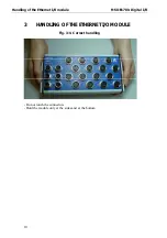
Fig. 3-1: Correct handling................................................................ 10
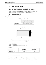
Fig. 4-1: Dimensions ........................................................................ 11
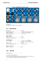
Fig. 4-2: MSX-E1701: View from above............................................ 12
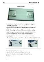
Fig. 5-2: Clamps.............................................................................. 16
Fig. 5-3: Angles pointing to the outside ........................................... 16
Fig. 5-4: Angles pointing to the inside ................................................ 16
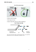
Fig. 5-5: Screws and seals ............................................................... 17
Fig. 5-6: Angle mounting ................................................................. 17
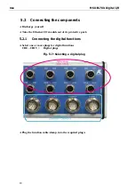
Fig. 5-7: Selecting a digital plug ...................................................... 18
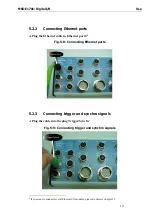
Fig. 5-8: Connecting Ethernet ports................................................. 19
Fig. 5-9: Connecting trigger and synchro signals ............................ 19
Fig. 5-10: Connecting the current supply ........................................ 20
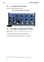
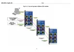
Fig. 5-11: Connecting several Ethernet I/O modules ....................... 21
Fig. 5-12: LEDs: Current supply, Ethernet and Status ........................ 22
Fig. 5-13: LEDs: Digital I/O ................................................................ 22
Fig. 6-1: Control signals MSX-E1701................................................. 25
Fig. 7-1: SOAP in the TCP/IP protocol staple ..................................... 28
Fig. 7-2: Board type list .................................................................... 31
Fig. 7-3: Settings .............................................................................. 31
Fig. 7-4: Settings OK......................................................................... 32
Fig. 7-5: Settings not OK................................................................... 32
Fig. 7-6: ADDIREG main window (example) ..................................... 33
Fig. 7-7: ADDevice Manager ........................................................... 33
Fig. 7-8: Board clear/insert ............................................................... 35
Fig. 7-9: SET MSX-Exxx: Main menu .................................................. 41
Fig. 7-10: New IP address changed ................................................ 44
Fig. 8-1: Block diagram ................................................................... 45
Fig. 8-2: Connection example: Digital inputs (24 V) ........................ 45
Fig. 8-3: Connection example: Digital outputs (24 V) ...................... 46
Tables
Table 5-1: LED “Status” .................................................................... 23
Table 6-1: Pin assignment: Ethernet Port 0 and Port 1..................... 25
Table 6-2: Pin assignment: Trigger/Synchro..................................... 26
Table 6-3: Pin assignment: Current supply ...................................... 26
Table 6-4: Pin assignment of the digital I/O .................................... 27
Table 7-1: Supported software functions ......................................... 37
Table 7-2: Supported software samples for the Ethernet I/O module
MSX-E1701...................................................................... 39
Table 7-3: Webserver: Further points................................................ 40
6