
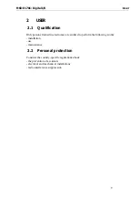


Use MSX-E1701:
Digital
I/O
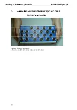
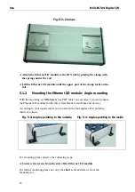
Fig. 5-2: Clamps
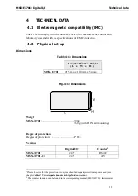
♦
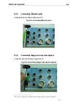
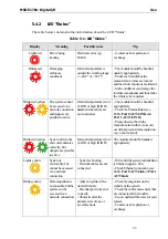
Attach the Ethernet I/O module to the DIN rail by placing the clamp with
the springs under the rail
♦
Lift the Ethernet I/O module until the upper part of the clamp locks on the
rail
5.1.2
Mounting the Ethernet I/O module: Angle mounting
With the mounting set
MX-Screw
(see PDF table “Accessories”) you can prepare
the Ethernet I/O module for the direct attachment to machines and devices.
According to your requirements you can attach the four angles either pointing
inside or outside.
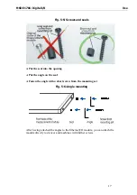
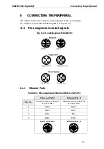
Fig. 5-3: Angles pointing to the outside
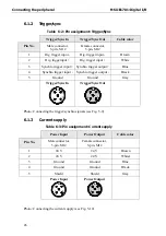
Fig. 5-4: Angles pointing to the inside
For mounting please observe the following steps:
♦
Unscrew the screws from the side of the Ethernet I/O module
For further mounting please use only the
short
seals and screws from the
mounting set.
16