Arnouse Digital Devices
User GuideSR10-FDD User Guide-V1.0_12-21-2020.docx
SR20-FDD
Version 1.0
© Arnouse Digital Devices 2022. All rights reserved.
Page 22 of 35
4.2.1
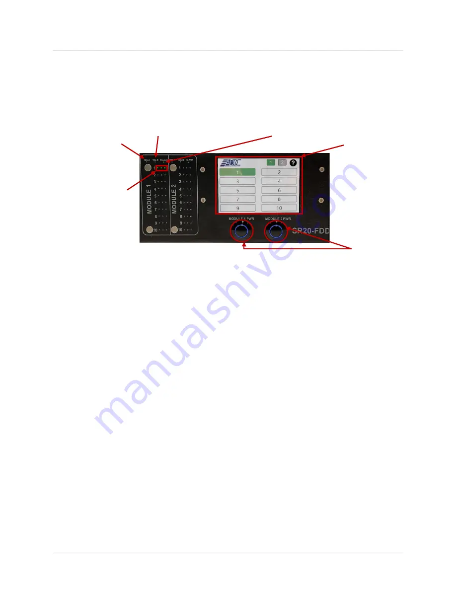
Front Panel
Figure 26- SR20-FDD Front Panel
4.2.2
Rear Panel
•
Refer to Figure 20
•
The Power OK green LEDs on the power supply will illuminate as soon as the
AC power cord is connected to a 20 Amp AC power receptacle.
•
The Fault amber LED will illuminate if there is a fault with the power supply.
Refer to the Murata
D1U54P-W-650-12-HB4C power supply manual for additional
information.
•
The 3 rear 60mm fans pull hot air out of the system and should be unobstructed.
Individual PC Card NIC
LEDs. One LED for each
1 GBPS NIC
10G-A: An SR-10’s primary
10Gbps SFP+ Port. Shown
as Port #32 in the SR-10
Switch Web GUI
10G-B: An SR-10’s
secondary 10Gbps SFP+
Port. Shown as Port #33 in
the SR-10 Switch Web GUI
1G-AUX: An SR-10’s
auxiliary 1Gbps Port. Shown
as Port #31 in the SR-10
Switch Web GUI
Touch Screen that can
control each individual card:
I.E. Reboot, shutdown,
power on
Module Power Buttons


