ADCP-80-575 • Issue 2 • December 2006
Page 22
© 2006, ADC Telecommunications, Inc.
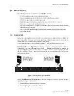
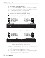
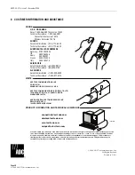
Figure 16. Alarm Contact Connections
4.5
Connecting Output Power
Output power is supplied to the equipment through screw-down barrier terminal strips located
on the rear of the chassis. Each bus has separate strips for each fuse type. The terminal screws
are of various sizes corresponding to the current load of the fuses. Each individual output has
two terminals, battery (BATT) and return (RTN).
Connections are typically made using spade-type or ring connectors crimped onto the output
power wires.
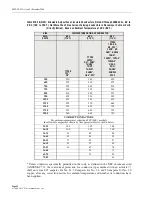
gives terminal screw size, maximum terminal width, and AWG
# accepted for copper wire. In selecting wire size, follow local code referring to the ampacity
guidelines provided in Appendix A of this manual.
Connect the output BATT and RTN terminals (see
) for each fused circuit to the
appropriate set of terminal strips. Use the appropriate wire size with appropriate size crimp-on
spade lugs or ring connectors or use the appropriate size wire with insulation stripped back at
the wire end. Tighten the screws to approximately 9 pound force-inches (1 Newton-meter) of
torque.
SCREW-DOWN BARRIER TERMINAL STRIP
WIRE-WRAP PIN TERMINAL BLOCK
17056-A
CONNECT TO CORRESPONDING
ALARM CONNECTORS
CONNECT TO REMOTE ALARMS
CONNECT TO REMOTE ALARMS
CONNECT TO CORRESPONDING
ALARM CONNECTORS
CONNECT TO AUDIO ALARMS
CONNECT TO VISUAL ALARMS
CONNECT TO REMOTE ALARMS
Summary of Contents for PowerWorx Power Distribution
Page 39: ......
Page 40: ...i www adc com ...


