ADCP-80-575 • Issue 2 • December 2006
Page 24
© 2006, ADC Telecommunications, Inc.
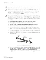
Use the following procedure to connect the input power cables to the fuse platform:
1. Obtain eight lengths of #2 AWG wire for use as the input power cables.
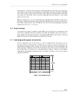
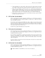
2. Strip back 7/8 inches of insulation from one end of each wire as shown in
.
3. Slide a 2-inch length of heat shrink insulation over the end of each wire.
4. Terminate one end of each wire with the 2-hole lug terminals provided (requires crimper).
5. Slide the heat shrink insulation down to the lug terminal so the barrel end of the terminal is covered.
6. Use a heat gun to apply heat to the heat shrink insulation until it tightens around the wire
and barrel end of the terminal.
7. Form each input cable into the shape required for connection to the input terminals and
secure to side of rack.
Figure 18. 2-Hole Lug Terminal Installation
8. Use the nuts (with captive star washers) provided to secure the input power wires to the
two input power terminals as shown in
. Each input power terminal has two
terminals, labeled BATT and RTN. Connect the wires to the terminals as follows:
a.
Battery wires
: Connect to BATT (–) terminals on the A and B input power terminal
blocks.
Warning:
Use of one bus only on a dual bus panel will result in false alarms for the unused bus.
Power is required on both buses on a dual bus panel for normal operation.
Caution:
Connect only the input voltage wire [the wire labeled BATTERY or BATT, or labeled
with the negative (–) voltage polarity and/or the voltage value] to the connector on the fuse
platform labeled BATTERY. Connect only the input return wire [the wire labeled RTN,
RETURN, or BATTERY GROUND, or labeled with the positive (+) voltage polarity] to the
connector on the fuse platform labeled RETURN.
Caution:
Caution should be taken to not reverse the input wires to the fuse platform. Within the
panel, the internal return wiring is not protected by fuses. If the wires are reversed, current will
flow through the unprotected return wiring in the panel to the equipment. This condition can
cause damage to the equipment in the frame in which the panel is installed and to equipment in
adjacent frames
17950-A
2-HOLE LUG
TERMINAL
HEAT SHRINK
TUBING
(2-INCH LENGTH)
#2 AWG
COPPER
WIRE
STRIP BACK 7/8 INCH
OF INSULATION
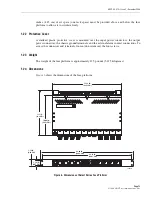
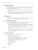
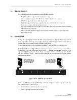
Summary of Contents for PowerWorx Power Distribution
Page 39: ......
Page 40: ...i www adc com ...


