background image

ADCP-80-575 • Issue 2 • December 2006

Page 9

© 2006, ADC Telecommunications, Inc.

Each input terminal block includes two pairs of 0.25-inch studs that are used for connecting the
BATT (battery –) and RTN () input power cables. Each pair of studs is mounted on
0.625 inch centers and accepts various size 2-hole compression lugs. The maximum lug width is
0.62 inches. 

Compression lugs for various sizes AWG wire are available as accessory items. Nuts with
captive washers are included to secure the compression lugs to the studs. The input terminal
blocks are located on the rear side of the panel. 

The minimum recommended wire size for the input power wiring is #2 AWG


copper wire. In

selecting wire size, follow local code referring to the ampacity guidelines provided in Appendix
A of this manual.

1.11 Output Power Connectors

Depending on the fuse configuration used, the fuse platform will have at least one, and up to
four, output power terminal blocks, located on the rear side of the platform. The number present
will depend on the fuse type and number of fuse positions. In general, there will be one terminal
block per bus for each fuse type present on that bus.

All of the output power terminal blocks are screw-down barrier terminal strips. The terminal
screws are of various sizes corresponding to the current load of the fuses. Each individual output
has two terminals, battery (BATT) and return (RTN). 

Copper wire is used for output power wiring. Connections are typically made using spade-type
or ring connectors crimped onto the output wires. 

Table 1

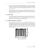
 gives terminal screw size, maximum terminal width, and accepted wire gauge. In

selecting wire size, follow local code referring to the ampacity guidelines provided in Appendix
A of this manual.

*

 Output terminal accepts wire sizes in the AWG range given; however, wire

size should be determined based on local requirements and practice.

Table 1. Output Power Terminal Blocks

FUSE
TYPE

FUSE HOLDER 
MODULE

TERMINAL 
SCREW SIZE

MAXIMUM
TERMINAL WIDTH

LUG/AWG 
RANGE 

*


KLM

All sizes

8-32

0.320 inch (8.128 mm)

#10 to #22

TPA

All sizes

8-32

0.320 inch (8.128 mm)

#10 to #22

GMT 

4- or 5-position

6-32

0.325 inch (8.255 mm)

#12 to #22

GMT

10-position

6-32

0.260 inch (6.604 mm)

#14 to #22

TPA/GMT

4 TPA fuses with

8-32

0.320 inch (8.128 mm)

#10 to #22

10 GMT fuses

3-48

0.200 inch (5.080 mm)

#16 to #24

Summary of Contents for PowerWorx Power Distribution

Page 1: ...ADCP 80 575 Issue 2 December 2006 1388844 Rev B PowerWorx Power Distribution Products Select Series Fuse Platform With Enhanced KLM Fuses User Manual 18858 A ...

Page 2: ...r disclaims any and all liability for indirect incidental special consequential or other similar damages This disclaimer of liability applies to all products publications and services during and after the warranty period This publication may be verified at any time by contacting ADC s Technical Assistance Center at 1 800 366 3891 extension 73475 in U S A or Canada or 952 917 3475 outside U S A and...

Page 3: ... 1 13 Alarm Contact Operation 10 1 14 Alarm Contact Connectors 10 1 15 Fuse Alarm Indicators 10 1 16 Power On Indicator 11 1 17 Fused Equipment Designation Card and Holder 11 1 18 Voltage Designation Label 12 1 19 Environmental Characteristics 12 1 20 Material and Finish 12 1 21 Cooling 12 1 22 Protective Cover 13 1 23 Weight 13 1 24 Dimensions 13 2 UNPACKING AND INSPECTION 14 3 PRE INSTALLATION 1...

Page 4: ...ng Voltage Designation Label 26 5 SYSTEM CHECK 26 5 1 Wiring Connections Torque Measurements 26 5 2 Power On and Connection Polarity Test 26 5 3 GMT Fuse Alarm Test and Installation 27 5 4 TPA Fuse Alarm Test and Installation 27 5 5 KLM Fuse Alarm Test and Installation 27 6 OPERATION 28 6 1 Clearing a KLM Fuse Alarm 28 7 MAINTENANCE 29 7 1 Inspection 29 7 2 Cleaning 29 7 3 Fuse Removal 29 8 CUSTOM...

Page 5: ...ular alert icon seen below and are listed in descending order of severity of injury or damage and likelihood of occurrence GENERAL SAFETY PRECAUTIONS Danger Danger is used to indicate the presence of a hazard that will cause severe personal injury death or substantial property damage if the hazard is not avoided Warning Warning is used to indicate the presence of a hazard that can cause severe per...

Page 6: ...munications Inc Warning Wet conditions increase the potential for receiving an electrical shock when installing or using electrically powered equipment To prevent electrical shock never install or use electrical equipment in a wet location or during a lightning storm ...

Page 7: ...aceable high brilliance power on green LED indicators one per bus Easy to remove plastic protective covers for input and output terminals Two hole compression lug terminals for input power connections Two grounding studs for robust and reliable ground connectivity Screw down barrier terminal strips for power output connections Relay contacts for alarms corresponding to red LEDs above The alarm con...

Page 8: ...GMT FUSED POWER OUTPUT TERMINALS BUS A GMT FUSED POWER OUTPUT TERMINALS BUS B KLM KTK FUSED POWER OUTPUT TERMINALS BUS A KLM KTK FUSED POWER OUTPUT TERMINALS BUS B GMT FUSE HOLDER 4 POSITION FRONT VIEW BUS A KLM KTK FUSE HOLDERS BUS A POWER ON INDICATOR GREEN LED BUS B POWER ON INDICATOR GREEN LED DESIGNATION CARD AND CARD HOLDER COVERS FOR INPUT POWER TERMINALS BUS A KLM KTK FUSE ALARM INDICATOR ...

Page 9: ...form All fuse platforms have power on LEDs that light in green indicating the presence of power and fuse alarm LEDs that light in red indicating a blown fuse In addition the fuse alarm LEDs on the enhanced KLM fuse platform have a green state indicating that a fuse is installed and receiving power Two types of alarm contacts are available wire wrap or screw down barrier terminal strip Two fuse pla...

Page 10: ...bination drive 12 24 pan head screws 4 and 12 flat washers 4 Used to secure the mounting brackets to the equipment rack 10 ring terminals 2 for 12 10 AWG wire Used to connect the grounding cables to the grounding studs Rear protective input terminal covers and output terminal covers Used to prevent accidental contact with the power input and output terminals The number of covers provided depends o...

Page 11: ...GROUND TERMINALS 10 RING TERMINALS FOR 12 10 AWG WIRE GROUNDING REAR COVERS FOR INPUT POWER TERMINAL BLOCKS DESIGNATION CARD PROTECTIVE COVER AND CARD HOLDER MOUNTING BRACKETS AND SCREWS FOR 19 INCH OR 23 INCH RACK INSTALLATION 3 8 INCH 9 525 MM 12 24 SCREWS AND 12 WASHERS 5 16 INCH 7 936 MM 8 32 FLAT HEAD SCREWS 19 INCH RACK MOUNTING BRACKETS 18876 A 23 INCH RACK MOUNTING BRACKETS ...

Page 12: ... or 2 inch 4 45 or 5 08 cm rack spaces 1 7 Power Buses The fuse platform is available with one or two separate power buses Each bus distributes the input power to multiple fused output circuits In each bus circuit current flows from the input connector to the fuse bus When a fuse is installed in a fuse holder the circuit is completed to the corresponding output connector Figure 3 provides a block ...

Page 13: ...use position It will remain green until there is a fuse failure or until a fuse is removed from that fuse holder At the time of a fuse failure or if the fuse is removed the LED will turn red and activate an alarm When the failed fuse is replaced the new fuse will act as described for the initial turn up turning green to indicate a power available condition At the same time the new fuse will clear ...

Page 14: ...at 100 Amps The following lists the maximum current that each type of fuse can provide TPA type fuse each fuse in four position module 50 Amps max KLM type fuse each fuse in two four or five position modules 30 Amps max GMT type fuse each fuse in four position module 15 Amps max GMT type fuse each fuse in 10 position module 10 Amps max 1 9 Input Voltage The fuse platform can accommodate 24 Vdc inp...

Page 15: ...e positions In general there will be one terminal block per bus for each fuse type present on that bus All of the output power terminal blocks are screw down barrier terminal strips The terminal screws are of various sizes corresponding to the current load of the fuses Each individual output has two terminals battery BATT and return RTN Copper wire is used for output power wiring Connections are t...

Page 16: ...vailable with either screw down barrier terminal strips or wire wrap pins for the alarm contact connections The following describes both types of contact connections Screw down barrier terminal strip Six terminals with 3 48 screws are mounted in a barrier type terminal block The terminals are on 0 25 inch 6 35 mm centers with a maximum distance between barriers maximum connecting terminal width of...

Page 17: ...isual power on indicator green LED for each power bus is mounted near the center of fuse platform front panel If present the LED when lighted indicates that power is being applied to the bus input connectors An unlighted LED indicates that power is not being applied The power on indicator LED can be replaced in the field 1 17 Fused Equipment Designation Card and Holder Two fuse designation cards s...

Page 18: ...tform and brackets are finished with powder paint that is putty white color 1 21 Cooling Vent openings are provided in the top and bottom of the fuse platform The vent openings allow convection cooling of all components without the use of fans or blowers A minimum of 1 75 Table 2 Fuse Platform Environmental Characteristics PARAMETER DESCRIPTION Operating temperature 5 C to 50 C Storage temperature...

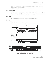
Page 19: ...output power connectors the chassis ground terminals and the external alarm contact connections To access the connectors and terminals loosen do not remove the four screws 1 23 Weight The weight of the fuse platform is approximately 12 5 pounds 5 675 kilograms 1 24 Dimensions Figure 6 shows the dimensions of the fuse platform Figure 6 Dimensions of Select Series Fuse Platform 17 13 IN 43 51 CM 11 ...

Page 20: ...a central office equipment room or restricted access location Observe the following guidelines when installing the fuse platform Mount the fuse platform in the upper area of the rack or cabinet to reduce exposure of the power wiring Provide a minimum of 1 75 inches 4 45 cm of air space one rack space above and below the fuse platform to allow air to freely circulate Be aware that adding a fuse pla...

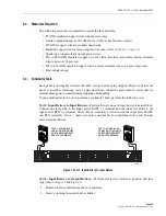
Page 21: ...s described here should be performed to verify that no internal damage has occurred during shipping and handling Using a multimeter that is set to perform a continuity check perform the following tests Test 1 Input Battery to Input Return Perform this test on each input power terminal block Connect one test probe to the input power BATT terminal and the other test probe to the input power RTN term...

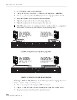
Page 22: ...r each input power position and fuse type refer to Figure 10 and Figure 11 1 Connect one test probe to the input power RTN terminal 2 Connect the other test probe to the RTN terminal on the output power terminal block 3 Verify that continuity exists between the specified terminals Note When done remove the working fuse from the fuse holder following completion of this test and reinstall an empty f...

Page 23: ...m fails any of the specified tests it is defective and must not be installed Contact ADC see Section 8 Customer Information and Assistance on page 30 for an RMA Return Material Authorization and to reorder if replacement is required 4 INSTALLATION This section provides procedures for mounting the fuse platform on a rack and installing wiring Wiring includes input grounding alarm and output wiring ...

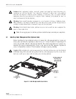
Page 24: ...perate maintain or otherwise come in contact with this equipment when the fuse platform is energized Only insulated tools should be used on energized elements of the fuse platform Warning Never install telephone equipment in a wet location or during a lightning storm When installing or modifying telephone lines disconnect lines at the network interface before working with uninsulated lines or term...

Page 25: ... to the width of the equipment rack into which the fuse platform will be installed 2 Orient the mounting brackets as shown in Figure 13 3 Attach the brackets to the sides of the fuse platform using the eight 5 16 inch 7 94 mm long flathead screws provided Tighten screws to 15 pound force inches 1 7 Newton meters of torque to insure grounding Figure 13 Mounting Brackets Note A fuse platform with th...

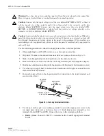
Page 26: ... terminal end of each wire to one of the studs and secure using the nuts with captive star washers provided requires 3 8 inch socket Tighten each stud nut to 23 pound force inches 2 6 Newton meters of torque 4 Route the free end of each chassis grounding wire to an approved office ground source 5 Cut each chassis grounding wire to length and connect it to the office ground source as required by lo...

Page 27: ...e is 3 48 Terminate wire leads with crimp on spade lug or ring connectors that have a maximum width of 0 200 5 080 mm or use 16 to 30 AWG copper wire without lugs insulation stripped back In selecting wire size follow local code referring to the ampacity guidelines provided in Appendix A of this manual Tighten the terminal screws to approximately 9 pound inches 1 Newton meter of force Wire wrap te...

Page 28: ...m terminal width and AWG accepted for copper wire In selecting wire size follow local code referring to the ampacity guidelines provided in Appendix A of this manual Connect the output BATT and RTN terminals see Figure 17 for each fused circuit to the appropriate set of terminal strips Use the appropriate wire size with appropriate size crimp on spade lugs or ring connectors or use the appropriate...

Page 29: ... to secure the compression lugs to the terminal block Caution Connecting the equipment to the wrong circuit may cause damage to the equipment or the fuse platform Make sure the fuse is the correct type and has the correct current rating as specified by the equipment manufacturer Note The continuous output load of the equipment during normal operation should not exceed 80 of the rated value of the ...

Page 30: ... two terminals labeled BATT and RTN Connect the wires to the terminals as follows a Battery wires Connect to BATT terminals on the A and B input power terminal blocks Warning Use of one bus only on a dual bus panel will result in false alarms for the unused bus Power is required on both buses on a dual bus panel for normal operation Caution Connect only the input voltage wire the wire labeled BATT...

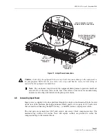
Page 31: ...he rear protective covers over the connectors at the rear of the fuse platform when all the wiring connections are completed To identify the covers see Figure 1 To install the plastic protective cover thread the four 3 8 inch 9 53 mm long Phillips drive 6 32 pan head screws into the standoffs located between the output power screw down terminal strips Rotate each screw approximately two turns to g...

Page 32: ... of the fuse platform 5 SYSTEM CHECK Perform the following procedures to check out the platform after completing installation 5 1 Wiring Connections Torque Measurements Measure the torque of all input output chassis ground and fuse alarm relay contact connections included in the non powered testing paragraphs above using a torque screwdriver that is calibrated in pound force inches Newton meters T...

Page 33: ...for that bank of fuses will change from unlit to lit red light and the fuse alarm relay will operate After testing remove the failed fuse and install a dummy fuse in any fuse position that will not be used To install a fuse replace the dummy fuse with a good fuse 5 4 TPA Fuse Alarm Test and Installation If the fuse platform being installed is equipped for TPA fuses use the following procedure to t...

Page 34: ...verify that the fuse alarm relay indicates an open circuit between the NO contact and the C contact at the fuse alarm contacts To install a KLM fuse insert the fuse in the selected position as in the procedure above Verify that the visual fuse alarm LED for that fuse is green 6 OPERATION All fuse platform circuits are operational as soon as power is applied to the input connectors The alarm indica...

Page 35: ...s Inspect for excessive dust and dirt that may block the vents 7 2 Cleaning If excessive dirt is found during the inspection brush or wipe dust and dirt from the fuse platform with a soft bristle brush or soft cloth Take care not to not damage the fuses or any wiring 7 3 Fuse Removal The GMT fuses can be removed with the aid of a wire hook or tweezers type fuse puller A fuse puller is available as...

Page 36: ...Extension 73475 Wireless Extension 73476 ASIA PACIFIC Sales Administration 65 6294 9948 Technical Assistance 65 6393 0739 ELSEWHERE Sales Administration 1 952 938 8080 Technical Assistance 1 952 917 3475 Italy 0800 782374 PRODUCT INFORMATION AND TECHNICAL ASSISTANCE Contents herein are current as of the date of publication ADC reserves the right to change the contents without prior notice In no ev...

Page 37: ...l Table 310 16 NEC Allowable Ampacities of Insulated Conductors Rated O Through 2000 Volts 60 to 90 C 140 to 194 F Not More Than Three Current Carrying Conductors in Raceway or Cable or Earth Directly Buried Based on Ambient Temperature of 30 C 86 F SIZE TEMPERATURE RATING OF CONDUCTOR AWG KCMIL 60 C 114 F 60 C 114 F 60 C 114 F TYPES TW UF TYPES FEPW RH RHW THHW THW THWN XHHW USE ZW TYPES TBS SA S...

Page 38: ... 650 735 2000 560 665 750 CORRECTION FACTORS For ambient temperatures other than 30C 86F multiply the allowable ampacities shown by the appropriate factor shown below 21 25 1 08 1 05 1 04 26 30 1 00 1 00 1 00 31 35 91 94 96 36 40 82 88 91 41 45 71 82 87 46 50 58 75 82 51 55 41 67 76 56 60 58 71 61 70 33 58 71 80 41 Table 310 16 NEC Allowable Ampacities of Insulated Conductors Rated O Through 2000 ...

Page 39: ......

Page 40: ...i www adc com ...

Reviews: