


32
American Dryer Corp.
113386-28
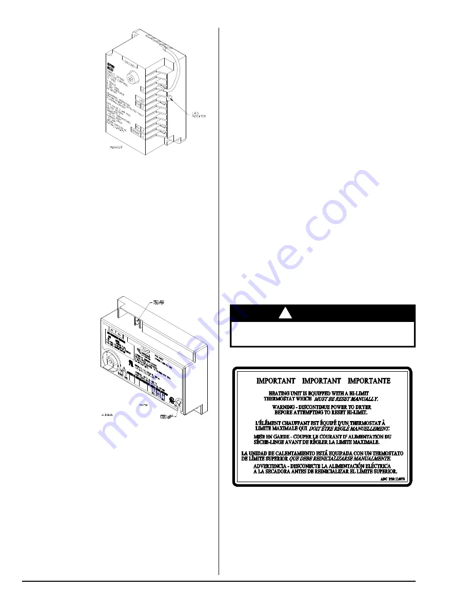
Theory of Operation:
Start the drying cycle. When the gas
burner ignites within the chosen trial for ignition time
(8-seconds), the flame sensor detects gas burner flame and
signals the DSI module to keep the gas valve open as long
as there is a call for heat. The DSI module will “LOCKOUT”
if the gas burner flame is not sensed at the end of the trial for
ignition period. The trial for ignition period will be repeated
for a total of three retries/trials (the initial try and two more
retries/trials). If the flame is not sensed at the end of the
third retry/trial (inter-purge period of 30-seconds), the DSI
module will “LOCKOUT” (a red L.E.D. diagnostic indicator
will flash).
An unlit red L.E.D. diagnostic indicator indicates normal
operation.
A lit green L.E.D. diagnostic indicator indicates dryer controller
is calling for heat and that all interlocks have been satisfied.
Manual Reset
Burner Hi-Limit Instructions __________
Phase 7
This dryer was manufactured with a manual reset burner hi-
limit thermostat, which is monitored by the Phase 7 computer.
If the burner hi-limit is open prior to the start of the drying
cycle, the dryer will start momentarily and then shut down,
the Phase 7 computer will display “BURNER HIGH LIMIT
FAULT” with an audio indication.
If the burner hi-limit opens during a drying cycle, the Phase 7
computer will also display the same error code described
above, along with an audio indication. If the drum temperature
is above 100° F (38° C), the dryer will continue to run with no
heat for 3 minutes or until the drum temperature has dropped
below 100° F (38° C). The clear/stop button on the Phase 7
keypad must be pressed to clear the error condition. The
open burner hi-limit must be reset “manually” prior to the start
of the next cycle.
Dual Timer / Phase 5
This dryer was manufactured with a manual reset burner hi-
limit thermostat. If the burner hi-limit is open prior to the start
of the drying cycle, or during the cycle, the dryer will not
recognize the open state of the burner hi-limit and will start
or continue through the drying cycle with no heat. Manual
reset hi-limit must be reset manually.
This hi-temperature condition may be caused due to a
restricted exhaust, poor airflow, or improper burner operation.
The location of the burner hi-limit is on the left side of the
burner box, looking at the burner from the back of the dryer.
!
WARNING
Discontinue power to dryer before attempting to reset
hi-limit.
For Models
with DSI Module
(Type I)
Theory of Operation:
Start the drying cycle. When the gas
burner ignites within the chosen trial for ignition time
(6-seconds), the flame sensor detects gas burner flame and
signals the DSI module to keep the gas valve open as long
as there is a call for heat. The DSI module will “LOCKOUT”
if the gas burner flame is not sensed at the end of the trial for
ignition period. The trial for ignition period will be repeated
for a total of three retries/trials (the initial try and two more
retries/trials). If the flame is not sensed at the end of the
third retry/trial (inter-purge period of 30-seconds) the DSI
module will “LOCKOUT” (L.E.D. diagnostic indicator flashes).
A steady L.E.D. indicator indicates normal operation.
No L.E.D. indicator indicates a power or an internal failure
has occurred.
For Models
with DSI Module
(Type II)
Summary of Contents for AD-120ES
Page 34: ...ADC Part No 113386 28 02 05 15...