800-357-104-01, Revision 01
18
September 29, 2000
HMS-357 List 4 and List 5
OC-3
After installing the cables, proceed the OC-3 fiber-optic cabling instructions.
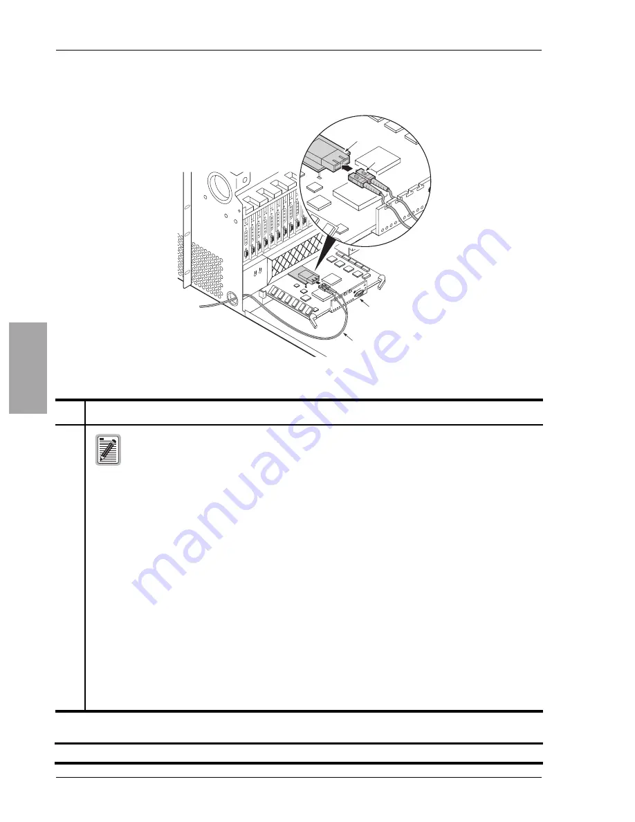
Figure 12.
Routing OC-3 Fiber-Optic Cables Through the Lower Access Hole (Left-Hand Side, Front View)
Step
Procedure
Installer Check
ü
ü
ü
ü
The steps the follow (
through
) provide OC-3 fiber-optic cabling
instructions that terminate at the multiplexer. This procedure requires a review the
HXU-369 multiplexer installation procedure. See
“Installing the HXU-369 Multiplexer Card”
for more information.
12
Route the network OC-3 fiber-optic cable through the access hole located on the lower, left-hand side
of the chassis and bring the cable to the front of the chassis.
H
13
Plug your ESD strap into the ESD input on the front of the chassis.
H
14
Align the edges of the HXU-369 with the slot guides in the multiplexer tray.
H
15
Grasping the card eject tabs, gently push the card halfway into the bay.
H
16
Remove the protective caps from the OC-3 fiber-optic cables.
H
17
Insert the fiber-optic-cable connectors into transmit (TX) and receive (RX) transceiver receptacles on
the piggybacked card.
Route the cables through the inverted T slots in the HXU-369 front panel. The inverted T slots provide
a method of maintaining the correct cable bend ratio.
H
18
Grasping the card eject tabs, gently push the card the remainder of the way into the bay.
H
19
Proceed to
“Wiring the Common Access Panel” on page 19
H
Installer Signature
?
?
?
?
Date
To fiber
network
Po
w
e
r
Fa
u
lt
C
ritic
a
l
M
a
jo
r
M
in
o
r
S
e
rv
ic
e
s
L
o
o
p
b
a
c
k
R
D
I
S
T
S
L
O
S
O
p
tic
O
n
A
c
tiv
e
Cl
as
s 1
La
se
r P
rod
uc
t
Pair
Gain
Po
w
e
r
F
ault
C
ritical
M
ajor
M
inor
S
er
vices
Loopbac
k
R
D
I
S
TS
LO
S
O
ptic O
n
A
ctiv
e
PairGain
Fiber cable
Tab
Transceiver
HXU-369


