background image

6. WIRING

Your 

FAST 250


comes equipped to be powered either 12 volts D/C or 100-277 volts A/C

(50/60 Hz). The required voltage should be noted on the end of the power cord that leads

into the enclosure.  If you are unsure what you’ve purchased, please contact us before

proceeding. Enlist the services of a licensed electrical contractor for installation assistance

if needed.

For A/C powered units

 the power cord exiting the back of the enclosure has 

three wires; a WHITE = Neutral lead, BLACK = Line (Hot), and GREEN = Ground.  

Please be cautious and take care to observe polarity of wires while installing.  If 

optional Data Recording System is purchased, an additional wire is included – 

WHITE = Data positive, BLACK = Data Negative, GREEN = Data.  

For D/C powered units

 WHITE = Positive, BLACK = Negative, and GREEN = Data 

(for the optional data collection unit).  

Section B – Operation 

7. POWER UP

Now that your enclosure is pole-mounted securely, the “YOUR SPEED” sign is affixed, and

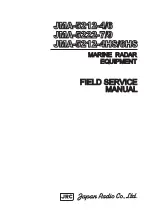
your wiring is completed, you are ready to power up.  Find the included key, insert into

the switch at the bottom, right side of the enclosure.  Turn clockwise ¼ turn to the “ON”

position.

When first turned on, the display will show a number between zero and 9. This number

indicates the brightness level of the display indicating the brightness is being set

automatically due to the surrounding sun light. 

Note:

 The brightness control is always on

automatic but it can be checked for proper operation by the user, if needed. To check this,

refer to the paragraph “Auto Intensity Diagnostic Mode, code 9981” in the Advanced

Features Section.

You will see there is a small programming push button located underneath the display at

one bottom corner (blue arrow 

Figure 4a

). This button or the remote will set all display

features.

        Figure 4a - Underside of Enclosure

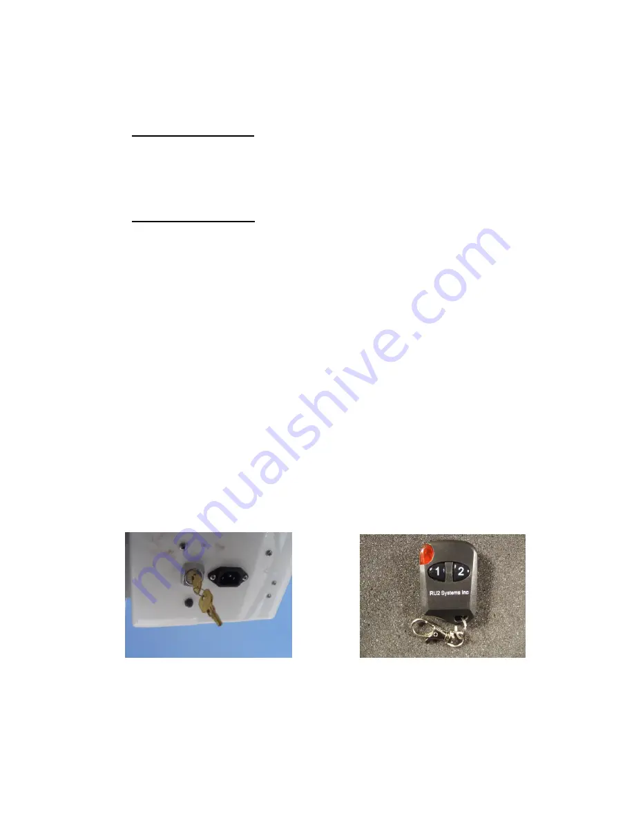
Figure 4b – Remote Key Fob 

Key Chain Remote Control 

The left button directs the numbers up with the other directing down. When

the sign is in run mode, holding both buttons in for 1 second resets the sign

without having to cycle the power key.

Adaptive Micro Systems LLC  |  7840 North 86th Street  |  Milwaukee, WI 53224 

Phone (800) 558-7022  |  AdaptiveDisplays.com

Summary of Contents for FAST 250

Page 1: ...FAST 250 Pole Mount Radar Speed Display Sign User Manual Adaptive Micro Systems LLC 7840 North 86th Street Milwaukee WI 53224 Phone 800 558 7022 AdaptiveDisplays com ...

Page 2: ...ogramming the Display 9 Readout Results 10 Advanced Features 11 Setting the Clock and Timer Section C Technical Information 12 Technical Specifications 13 Options and Upgrades 14 Warranty 15 Trouble Shooting Tips 16 Contact Information Section D Optional Data Recording System Quick Setup Guide In Depth Setup Guide Adaptive Micro Systems LLC 7840 North 86th Street Milwaukee WI 53224 Phone 800 558 7...

Page 3: ...Figure 1b Section A Installation 2 LOCATION SELECTION In order to optimize your traffic calming results there are a few simple things to keep in mind and simple steps to follow You ll want a mounting location that s on a relatively flat stretch of road and is not too close to any stop signs intersections or sharp curves in the road A clear line of sight relatively free of obstructions such as larg...

Page 4: ...ng up vehicles too far away simply rotate the unit clockwise so that it s facing the opposite curb a bit more Likewise if the unit is picking vehicles up too close or not far away enough rotate counter clockwise Remember you may adjust the radar gun angle aim in the FAST 250 as well as the mounting angle of the enclosure on the pole for maximum fine tuning Figure 3b Figure 3a Dialing in Approach A...

Page 5: ...ed you are ready to power up Find the included key insert into the switch at the bottom right side of the enclosure Turn clockwise turn to the ON position When first turned on the display will show a number between zero and 9 This number indicates the brightness level of the display indicating the brightness is being set automatically due to the surrounding sun light Note The brightness control is...

Page 6: ...L Blank Violator Alert MENU Min speed for sign to display Speed at which red SLOW shows Optional Feature Flashing Red Blue speed Optional Feature Speed at which to flash readout Speed at which to blank screen ND No Display Unit collects radar data with no display OPTIONAL ONLY for units with the optional data collection software feature Feature must be enabled See Advanced Features Mode Section SE...

Page 7: ...y power only Violator Alert Violator Alert 1 MS Minimum Speed After seeing the VA screen the display will show MS see photo below along with a number The number represents the lowest speed at which the display will start showing all oncoming vehicles When this number appears the operator has 5 seconds within to start pushing the button in order to program this MS speed setting Press the button unt...

Page 8: ...d wait for the next screen after approximately 5 seconds Violator Alert 3 RB Red and Blue flashing lights Optional Feature Check your packing slip or order to verify that this optional feature has been included with your product If this feature was ordered the display will now show RB which effectively flashes the Red and Blue flashing light pattern at the driver while displaying their speed The o...

Page 9: ... time Notes After this last BL screen all of the violator alert settings have been saved even after the sign is switched off When the sign is turned on again it will run thru all of the modes and their speed settings for the operator to review If changes are needed press the sign mounted button for 5 seconds which will start the mode settings to display again If using the key chain remote hold the...

Page 10: ...etected Minimum Speed limit at 5 mph the SLOW message at 35 Flashing Speed at 40mph the Red Blues at 50 and the Blanking Speed at 60 This is what will happen Oncoming vehicles speeds will be shown on the sign traveling from 5 to 34 MPH If the vehicle is traveling 35 to 39 the SLOW message will flash Between 41 and 49 their speed will be displayed while flashing Over 50MPH the display will show the...

Page 11: ...eatures A B C D 9 9 6 9 9 9 7 1 9 9 7 3 9 9 7 5 9 9 7 9 9 9 8 1 9 9 8 3 9 9 8 7 9 9 8 9 Minimum Speed Mode Alternate Slow Violator Alert Mode Demo mode see further instructions Show Serial Number Display Diagnostic Mode Auto Intensity Diagnostic Mode Turn On Off Radar Acceleration Filter Turn On Off No Display Availability Turn On Off Set Time Availability Minimum Speed Mode Lower speeds of 5 mph ...

Page 12: ...lity to auto adjust the brightness of the display according to the ambient light A small sensor in the center of the sign reads the outside light so the processor may determine how bright to make the display Once in this mode the outside light can be varied and will show a number from 0 to 9 with 0 being the lowest and 9 the highest Putting your hand over the sensor can change this reading Turning...

Page 13: ...tivate this function Once the feature is activated you will see the following codes added to the startup display setting TIMER CODE CHART ST Set Time EN Enable DS Disable OH OM On Hour On Minute FH FM Off Hour Off Minute HR Hour MN Minutes Time Set Menu Turn on the timer feature Turn off the timer feature Hour at which sign is to turn on Minute at which sign is to turn on Hour at which sign is to ...

Page 14: ...ions Shipping Weight Operational Temperature Range Speed detection range 26 Wide x 20 5 Tall x 9 Deep 40 Lbs 22 degrees F to 158 degrees F 5 99 mph b Casework i 1 8 thick welded aluminum construction front panel access to critical components ii All stainless steel hardware iii White powder coat finish inside and out custom colors available iv MUTCD compliant YOUR SPEED reflective sign included v L...

Page 15: ... If no speed is displayed 1 Check battery s with a voltage meter to be sure they are outputting at least 12 volts 2 Check battery charger indicator lights Be sure there is power to the charger from your outlet and power out from the charger measures higher than 12 volts 3 Check your Set Time feature and be sure your clock is set properly to display at the correct times If in doubt disable the set ...

Page 16: ...ad screw driver into the grove and gently turning counter clockwise 16 ADAPTIVE CONTACT INFORMATION Adaptive Micro Systems LLC 7840 North 86th Street Milwaukee WI 53224 Phone 800 558 7022 AdaptiveDisplays com Address Adaptive Micro Systems LLC 7840 N 86th Street Milwaukee WI 53224 Phone Number 800 558 7022 Website adaptivedisplays com Email connect adaptivedisplays com ...

Page 17: ...ting traffic data hold any key and the display will read Remove SD Card b To remove the card press the SD card in and it will pop out 3 Setting the Date and Time Figure 2 Set Time a Before inserting the SD card first power up as described above Next press Enter to get to the Settings Menu Figure 2 b Press Enter when the display reads Set Time c Using the and keys set the correct Month Day Year Hou...

Page 18: ...e display will turn off after 1 minute of inactivity from the user If a card is in the unit it will continue recording data and display speeds Figure 3 Press any key to turn on the backlight again Figure 3 Speed of oncoming vehicles being recorded The data is saved in an ASCII text format and can be viewed using the Traffic Count 7 or you can create your own reports and graphs with the raw data an...

Page 19: ... day Each file can list for example the street name so when you are ready to run the reports you can easily identify each location If you have multiple trailers signs each unit can have a unique name or number a Make Your File Name The file name is 8 characters long and can be any combination of letters numbers and spaces The default file name is in MMDDYY RU2 format If the first file is not delet...

Page 20: ... Type and Radar Speed should only be changed if directed by an authorized technician 2 Error Messages ERR Card Lost Press any Key If the SD card is removed without stepping thru the saving data section this error will appear Go back to Section 1 to record new data Note Data is written to the card as vehicles are recorded The data can be recovered if the card is not cleared Write Error Card Error T...

Reviews: