


2.1
BOILER ROOM
2.1.1
ACCESSIBILITY
The boiler room must be large enough to allow proper access to the
boiler. The following minimum distances (mm) around the boiler are
required:
- at the front
500
- at the sides
100
- at the rear
150
- above
700
2.1.2
VENTILATION
The boiler room must be fitted with top and bottom vents as shown in
the table below.
2.1.3
BASE
The boiler must be laid on a base made of non-combustible materials.
2.2
CONNECTIONS
2.2.1
CHIMNEY CONNECTION
The boiler can be connected to a suitable flue or to chimney by a metal
pipe rising at an angle from the boiler to the chimney. It must be easily
removable in order to give access to the flue pipes when servicing the
boiler. A draught regulator must be installed on the chimney in order to
stabilise negative pressure.
Because of their high level of performance our boilers
produce flue gas discharge at low temperatures. This
can cause condensation in some chimney flues. Your
installing engineer will advise you whether you need to
install a flue pipe in your chimney.
Important
Boilers must be installed by an approved engineer, in
accordance with current local standards and regulations.
2.2.2
CENTRAL HEATING CONNECTION
2.2.2.1
Examples of basic circuit configurations
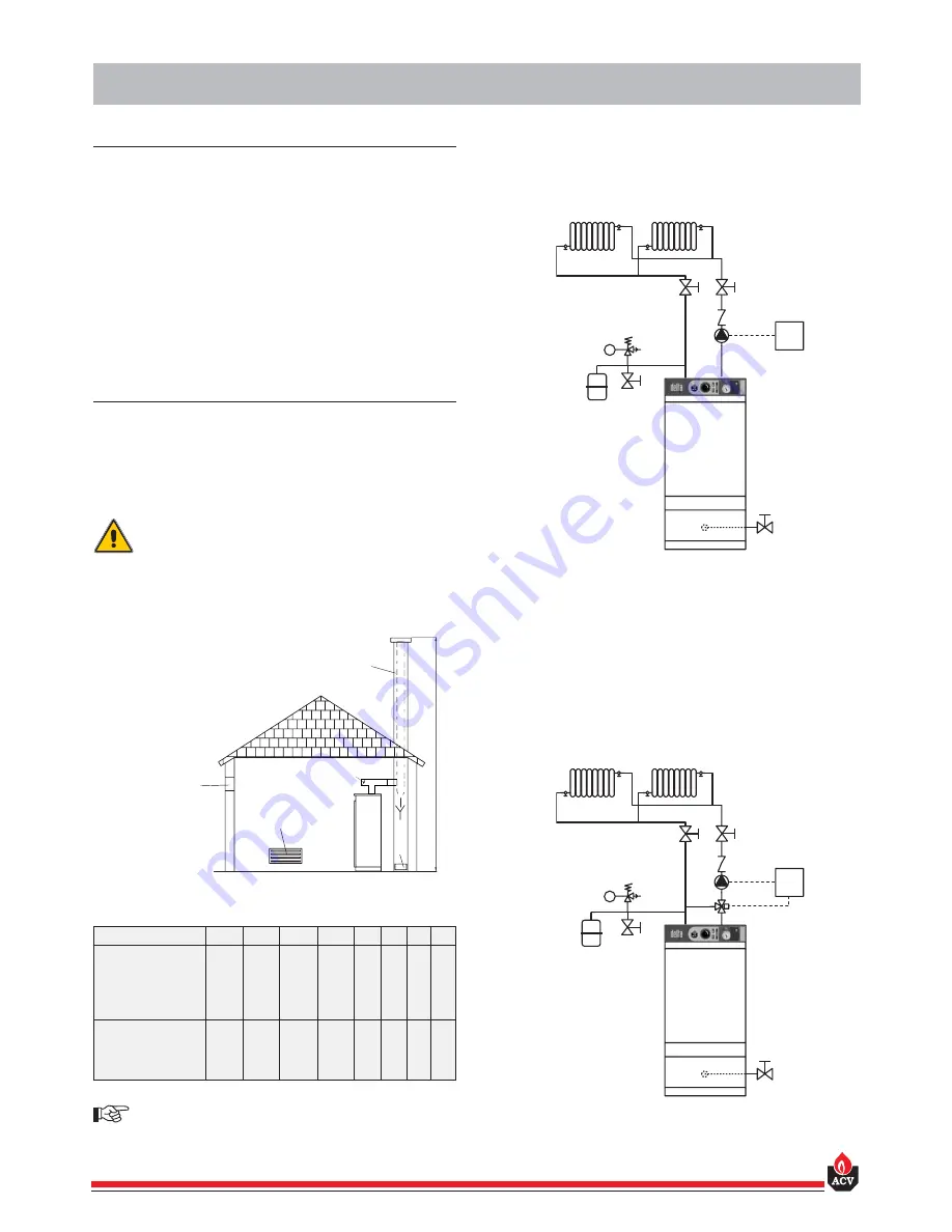
The drain cock and safety valve must be connected to the waste
water disposal system.
1. Motorised 3-way manual mixer valve
2. Safety valve preset to 3 bar with pressure gauge
3. Circulator
4. Non-return valve
5. System filling valve
6. Expansion tank
7. Room thermostat (fig. 2)
8. ACV 13 controller (see controller kit on page 5) (fig. 3)
9. Central heating isolation valve
10. Discharge outlet
Fig. 2: Hydraulic diagram showing circulator controlled
by a room thermostat.
2
INSTALLATION
6
2
3
4
7
5
9
9
10
1
6
2
3
4
8
5
9
9
10
Fig. 3: Hydraulic diagram with motorised mixer valve
Fig. 1: Boiler room ventilation and chimney connection
A
B
F
D
C
E
A.
Top vent
B.
Bottom vent
C.
Draught regulator
D.
Inspection cover
E.
Chimney height
F.
Chimney diameter
3
Ventilation
25-F25
35-F35
45-F45
55-F55
G25
G35
G45
G55
Min. fresh air
requirement
m
3
/h
50/66
66/90
84/122
100/138
45
63
81
99
Top vent (A)
dm
2
2
2
2
2
1,5
1,5
1,5
1,5
Bottom vent (B)
dm
2
1,5
1,5
1,5
1,5/2,1
1,5
1,5
1,5
1,7
Chimney
E = 5m
Ø min.F
mm
158/182
182/213 208/248
226/266
160
189
215
236
E = 10m
Ø min.F
mm
133/153
153/179 175/209
190/223
135
159
181
199
E = 15m
Ø min.F
mm
130/138
138/162 158/188
172/202
130
143
163
179


