ActronAir Serene WRC-026AS Installation Manual Download Page 24

Page 24

8. Wiring

Serene Wall Hung Split System

Safety Precautions


WARNING 


•  Be sure to isolate the power supply before working  

    on the unit.
•  All electrical wiring must be done according to local and  

    national regulations.
•  Electrical wiring must be done by qualified technician.  

    Improper connections may cause electrical malfunction,  

    injury and fire.
•  Connect the power cable to the terminals and fasten it  

    with the clamp. Unsecured connection may cause fire.
•   Make sure that all wiring is done correctly and the  

    control board cover is properly installed. Failure to do  

    so can cause  overheating at the connection points, fire,     
    and electrical shock.


CAUTION

•  Make sure you earth the unit. Improper earthing may       

cause electrical shock.

•  

DO NOT

 connect the unit with the power source until  

   all wiring and piping is completed.
•  Make sure that you do not cross your electrical wiring  

   with your signal wiring, as this can cause distortion and  

   interference or unit malfunction. 

Follow these instructions to prevent distortion when the 
compressor starts:

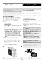
• The unit must be connected to its individual sub-circuit.

Ensure sub-circuit mains are of adequate size to ensure 
minimal voltage drop at supply terminals.

• No other equipment should be connected to the same  
   sub-circuit as the A/C unit.

• The unit’s power information can be found on the rating  
   sticker on the product.

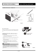
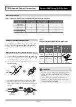
1.    Prepare the cable for connection 

       a.    Ensure the correct size cable size has been selected,         
              as per specifications. 

       b.    Using wire strippers, strip the rubber jacket from  
               both ends of signal cable. 
       c.    Strip the insulation from the ends of the wires. 
       d.    Using a wire crimper, crimp fork-lugs on the ends of  
               the wires.

Outdoor Unit Wiring


WARNING 


Before performing any electrical or wiring work, isolate 

and lock out/tag out power to the A/C unit.
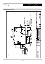
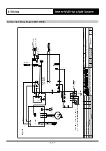
 

NOTE


While connecting the wires, please strictly follow the

  wiring diagram (found inside the electrical box cover).


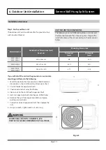
TAKE NOTE OF FUSE SPECIFICATIONS


The air conditioners circuit board (PCB) is designed with 


a fuse to provide overcurrent protection. The 


specifications of the fuse are printed on the circuit 


board, such as: T5A/250VAC, T10A/250VAC, etc.

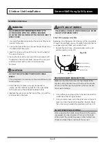
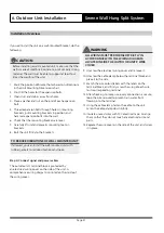
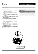
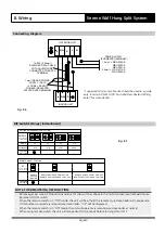
2.    Remove the electric cover of the outdoor unit. If there  
        is no cover on the outdoor unit,disassemble the bolts  
        from the maintenance board and remove the  
        protection  board. (See fig 8.1)


3.    Connect the fork-lugs to the terminals.  Match the wire  
        colours / labels with the labels on the terminal block,          
        and firmly screw the lug of each wire to its  
        corresponding terminal.

4.    Clamp down the cable with designated cable clamp.

5.    Reinstall the cover of the electric control box.

Fig. 8.1

Screws

Cover

Summary of Contents for Serene WRC-026AS

Page 1: ...your new air conditioning unit and keep it near the unit for future reference INSTALLATION MANUAL Wall Hung Split System Air Conditioner Model Numbers WRC 026AS WRE 026AS WRC 035AS WRE 035AS WRC 050A...

Page 2: ...door Unit Installation 09 5 Outdoor Unit Installation 18 6 Refrigerant Piping Connection 22 7 Parts Overview 08 4 Table of Contents Installation Manual Leak Test and Air Evacuation 32 9 Electrical and...

Page 3: ...nstalled in accordance with national regulations Failure to observe a caution may result in injury or equipment damage CAUTION Note about Fluorinated Gases 1 This air conditioning unit contains fluori...

Page 4: ...damaged 6 This appliance is not intended for use by young children or infirm persons unless they have been adequately supervised by a responsible person to ensure that they can use the appliance safel...

Page 5: ...ult in water leakage electrical shock fire or cause the equipment to fail Name Shape Quantity Installation template 174mm 230mm 55mm 1 Mounting plate 1 Clip anchor 5 Mounting plate fixing screw ST3 9...

Page 6: ...e 6 12cm 2 3m 12cm 15cm Select Installation Location Attach Mounting Plate Drill Wall Hole Determine Wall Hole Position 1 2 3 4 3 Installation Summary Serene Wall Hung Split System Installation Overvi...

Page 7: ...on Summary Serene Wall Hung Split System Installation Overview Mount Indoor Unit 1 L 2 N S Connect Wiring Prepare Drain Hose Connect Piping 5 6 7 Leak test and evacuate the refrigeration system 8 Perf...

Page 8: ...Page 8 4 Parts Overview Serene Wall Hung Split System Fig 4 1 Parts Overview...

Page 9: ...devices e g TV radio computer DO NOT install unit in the following locations Near any source of heat steam or combustible gas Near flammable items such as curtains or clothing Near any obstacle that...

Page 10: ...n of Mounting Plate Step 3 Drill wall hole for connective piping You must drill a hole in the wall for refrigerant piping the drainage pipe and the signal cable that will connect the indoor and outdoo...

Page 11: ...nit Outline 55 Installation Overview MOUNTING PLATE DIMENSIONS Different models have different mounting plates In order to ensure that you have ample room to mount the indoor unit the diagrams to the...

Page 12: ...it Any dents in the piping will affect the unit s performance If refrigerant piping is already embedded in the wall do the following Step 1 Hook the indoor unit on the mounting plate Keep in mind that...

Page 13: ...Based on the position of the wall hole relative to the mounting plate choose the side from which the piping will exit the unit 2 If the wall hole is behind the unit keep the knock out panel in place...

Page 14: ...ver it can also be attached to the right hand side 1 To ensure proper drainage attach the drain hose on the same side that your refrigerant piping exits the unit 2 Attach drain hose extension purchase...

Page 15: ...OUT TAG OUT PROCEDURES TO BE USED ETC Step 6 Connect signal cable The signal cable enables communication between the indoor and outdoor units You must first choose the right cable size before preparin...

Page 16: ...ic panel on the back NOTE ABOUT WIRING THE WIRING CONNECTION PROCESS MAY DIFFER SLIGHTLY BETWEEN UNITS Step 7 Wrap piping and cables Before passing the piping drain hose and the signal cable through t...

Page 17: ...ire through the hole in the wall 4 Hook the top of the indoor unit on the upper hook of the mounting plate 5 Check that unit is hooked firmly on mounting by applying slight pressure to the left and ri...

Page 18: ...will not disturb others Protected from prolonged periods of direct sunlight or rain 6 Outdoor Unit Installation Serene Wall Hung Split System Installation Instructions Outdoor Unit PRIOR TO INSTALLAT...

Page 19: ...0 until it clicks in place facing the front of the unit 4 Connect a drain hose extension not included to the drain joint to redirect water from the unit during heating mode IN COLD CLIMATES In cold cl...

Page 20: ...end of each expansion bolt 5 Hammer expansion bolts into the pre drilled holes 6 Remove the nuts from expansion bolts and place outdoor unit on bolts 7 Put washer on each expansion bolt then replace t...

Page 21: ...uce vibrations and noise Step 4 Connect signal and power cables The outside unit s terminal block is protected by an electrical wiring cover on the side of the unit A comprehensive wiring diagram is p...

Page 22: ...the air tight seal of refrigerant piping connections 3 Place flare nuts on both ends of pipe Flare each end of connecting pipes 4 Connect the pipe to indoor and outdoor unit Apply a thin coat of refr...

Page 23: ...e valve Do not grip the nut that seals the service valve See Fig 7 4 USE SPANNER TO GRIP MAIN BODY OF VALVE Torque from tightening the flare nut can snap off other parts of valve 4 While firmly grippi...

Page 24: ...should be connected to the same sub circuit as the A C unit The unit s power information can be found on the rating sticker on the product 1 Prepare the cable for connection a Ensure the correct size...

Page 25: ...th a fuse to provide overcurrent protection The specifications of the fuse are printed on the circuit board such as T3 15A 250VAC T5A 250VAC etc 1 Prepare the cable for connection a Using wire strippe...

Page 26: ...uction modification and or distribution are prohibited without written consent Revision Description C WD3002 Rev Description Date By PCR ORIGINAL A4 Size Base Model No Variation Variation Code A Drawi...

Page 27: ...Ltd Reproduction modification and or distribution are prohibited without written consent Revision Description C WD3013 Rev Description Date By PCR ORIGINAL A4 Size Base Model No Variation Variation Co...

Page 28: ...roduction modification and or distribution are prohibited without written consent Revision Description C WD3014 Rev Description Date By PCR ORIGINAL A4 Size Base Model No Variation Variation Code A Dr...

Page 29: ...modification and or distribution are prohibited without written consent Revision Description C WD3015 Rev Description Date By PCR ORIGINAL A4 Size Base Model No Variation Variation Code A Drawing No D...

Page 30: ...ON OFF FUNCTION Remove jumper wire in CN46 terminal and set F2 dip switch as above in the multi function control board to use Remote ON OFF switch When the remote switch is in OFF mode the unit will...

Page 31: ...y Installer SUB MAINS CIRCUIT BREAKER 2 3 1 INDOOR UNIT Move to left or right 30 50mm 30 50mm MAINS WIRING 220 240VAC Single Phase Neutral 50Hz CONTROL WIRING 220 240VAC Single Phase Neutral 50Hz 3 2...

Page 32: ...drop during this time To indoor unit N I T R o G E N refrigerant pipes 4000 kPa leak test for 1 hour Leak Test Fig 9 1 CAUTION Use a vacuum pump and a vac stat reading lower than 500 microns and an ai...

Page 33: ...nutes then check that there has been no change in system pressure Flare nut Cap Valve body Valve stem Fig 9 2 9 Leak Test and Air Evacuation Serene Wall Hung Split System Overview OPEN VALVE STEMS GEN...

Page 34: ...lways use protective gear when charging the system DO NOT mix refrigerant types Some systems require additional charging depending on pipe lengths The standard pipe length is 15m The additional refrig...

Page 35: ...ALL WIRING MUST COMPLY WITH LOCAL AND NATIONAL ELECTRICAL CODES AND MUST BE INSTALLED BY A LICENSED ELECTRICIAN Gas Leak Checks Proper pressure test with dry nitrogen should be performed prior to air...

Page 36: ...the MODE button to scroll through the following functions one at a time COOL Select lowest possible temperature HEAT Select highest possible temperature 4 Let each function run for 5 minutes and perfo...

Page 37: ...emperature is below 17 C In this instance you can use the MANUAL CONTROL button to test the COOL function 1 Locate the MANUAL CONTROL button on the right hand side panel of the unit See Fig 10 1 2 Pre...

Page 38: ...ironment in order to maintain your system s proper operating performance High discharge pressures are good indication that the coils need cleaning When using detergent or solvents to clean the coils f...

Page 39: ...e than 1M Heat Exchanger Check for clogging by dust Check for leaks damage Clean air inlet side as necessary Straighten any bent fins using fins comb Drain Pan Condensation line Check for obstructions...

Page 40: ...w of water Clean to eliminate obstructions sludge check condition of drain line Pour water to ensure free flow Compressor Check for high low pressure Measure insulation resistance Check compressor for...

Page 41: ...Page 41 Notes Serene Wall Hung Split System...

Page 42: ...Page 42 Notes Serene Wall Hung Split System...

Page 43: ...Page 43 Notes Serene Wall Hung Split System...

Page 44: ...actronair com au 1300 522 722 Copyright 2016 Actron Engineering Pty Limited ABN 34 002 767 240 Registered Trade Marks of Actron Engineering Pty Limited Installation Document 9590 5000 Ver 5 190325...

Reviews: