


Page 15
5. Indoor Unit Installation
Serene Wall Hung Split System
BEFORE PERFORMING ELECTRICAL
WORK, READ THESE REGULATIONS
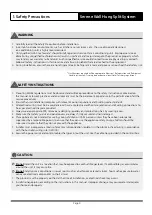
1. All wiring must comply with local and national electrical
codes, and must be installed by a licensed electrician.
2. All electrical connections must be made according to the
Electrical Connection Diagram located on the panels of
the indoor and outdoor units.
3. Power voltage should be within Australian Standards
230VAC (+10%, -6%) 50Hz. Insouciant power supply can
cause malfunction, electrical shock, or fire.
4. Correct sized circuit breaker must be installed.
5. Only connect the unit to an individual final sub-circuit.
Do not connect another appliance to that sub-circuit.
6. Make sure to properly earth the air conditioner.
7. Every wire must be firmly connected. Loose wiring can
cause the terminal to overheat, resulting in product
malfunction and possible fire.
8. Do not let wires touch or rest against refrigerant tubing,
the compressor, or any moving parts within the unit.
WARNING
BEFORE PERFORMING ANY ELECTRICAL OR
WIRING WORK, ISOLATE POWER TO UNIT.
CORRECT LOCKOUT/TAG OUT PROCEDURES TO BE
USED ETC.
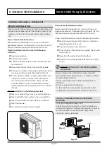
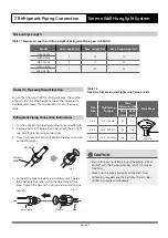
Step 6: Connect signal cable
The signal cable enables communication between the
indoor and outdoor units. You must first choose the right
cable size before preparing it for connection.
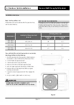
CHOOSE THE RIGHT CABLE SIZE
The size of the power supply cable, signal cable, fuse, and
switch needed is determined by the maximum current
of the unit. The maximum current is indicated on the
nameplate located on the side panel of the unit. Refer
to this nameplate to choose the right cable and refer to
AS3000 and local wiring rules and etc.
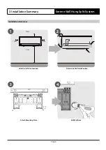
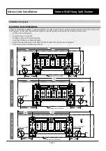
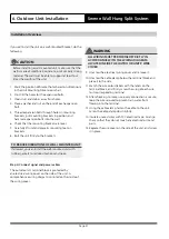
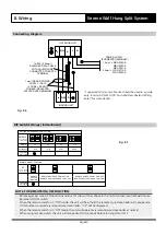
Installation Overview
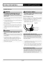
TAKE NOTE OF FUSE SPECIFICATIONS
The air conditioner’s circuit board (PCB) is designed
with a fuse to provide overcurrent protection. The
specifications of the fuse are printed on the circuit board,
such as: T3.15A/250VAC, T5A/250VAC, etc.
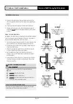
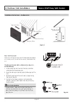
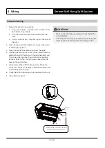
1. Prepare the cable for connection:
a. Using wire strippers, strip the outer insulation from
both ends of signal cable to reveal about 40mm of the
wires inside.
b. Strip the inner insulation from the ends of the wires.
c. Using wire crimper, crimp u-type lugs on the ends of
the wires.
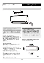
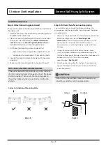
2. Open front panel of the indoor unit by loosening the
screws according to picture Fig. 5.7, which provide big
space for wiring connection.
3. Open the wire box cover to connect the cable.