


Page 13
Fig. 4.7
Fig. 4.8
Knock-out Panel
Fig. 4.9
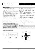
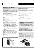
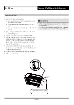
3. Use the holder in the mounting plate to prop up the
unit, giving you enough room to connect the refrigerant
piping, signal cable, and drain hose.
Fig. 4.7
Fig. 4.8
Knock-out Panel
Fig. 4.9
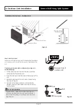
Step 3.
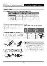
Connect drain hose and refrigerant piping (refer to
Refrigerant Piping Connection
section of this manual for
instructions).
Step 4.
Keep pipe connection point exposed to perform
the leak test (refer to
Electrical Checks and Leak Checks
section of this manual).
Step 5.
After the leak test, wrap the connection point with
insulation tape.
Step 6.
Remove the bracket or wedge that is propping with
insulation tape.
Step 7.
Using even pressure, push down on the bottom half
of the unit. Keep pushing down until the unit snaps onto
the hooks along the bottom of the mounting plate.
If there is no refrigerant piping embedded in the wall, do
the following:
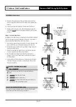
1. Based on the position of the wall hole relative to the
mounting plate, choose the side from which the piping
will exit the unit.
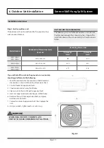
2. If the wall hole is behind the unit, keep the knock-out
panel in place. If the wall hole is to the side of the indoor
unit, remove the plastic knock-out panel from that side
of the unit. (See
Fig. 5.9
). This will create a slot through
which your piping can exit the unit. Use needle nose
pliers if the plastic panel is too dicult to remove by hand.
Fig. 4.7
Fig. 4.8
Knock-out Panel
Fig. 4.9
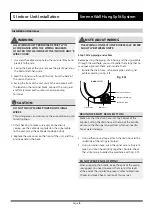
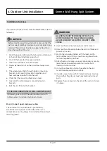
3. Use scissors to cut down the length of the insulating
sleeve to reveal about 40mm of the refrigerant piping.
This serves two purposes:
• To facilitate the
Refrigerant Piping Connection
process
• To facilitate Gas Leak Checks and enable you to
check for dents
4. Connect the indoor unit’s refrigerant piping to the
connective piping that will join the indoor and outdoor
units. Refer to the
Refrigerant Piping Connection
section of this manual for detailed instructions.
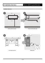
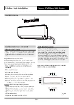
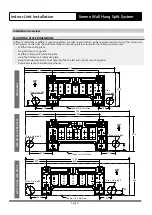
5. Indoor Unit Installation
Serene Wall Hung Split System
Installation Overview
Fig. 5.7
Fig. 5.8
Fig. 5.9